84 Rev 2.2 • 27 Mar 10
2. Installation
Making Alarm Connections
3 Connect the other end of the cable to an external alarm indicator. See “Alarm Indicator Equip-
ment” on this page for information on wiring the DE9 connector.
Alarm Indicator Equipment
An external alarm indicator can be created to display visual cues when a failure has occurred on the
NV8000 power supply or a NV8500 family router frame. LEDs can be wired to specific pins on a
DE9 connector. Each LED indicates what specific router module has failed.
• For NV8000 power supply alarms, see NV8000 Power Supply
on page 84.
• For NV8500 family router alarms, see Router Alarms
on page 84.
NV8000 Power Supply
The ‘Alarms’ connection on the rear of the NV8000 uses a DE9 connector. An “alarm” or ON con-
dition occurs when the connection between an alarm pin and Alarm_COM (common) opens. The
alarm turns OFF when the connection between Alarm_COM and the alarm pin closes again. If a
PS8100 power supply module is removed, the alarm circuit remains open.
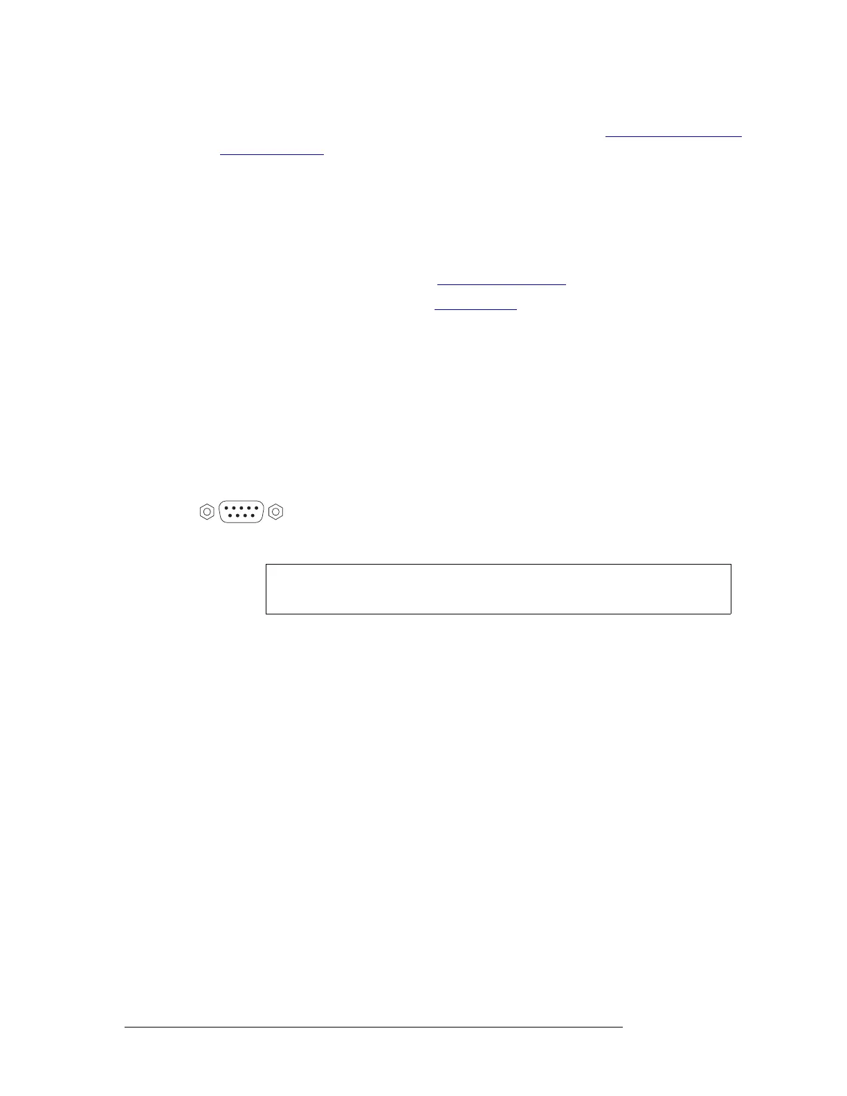
For an external alarm indicator box, connect to the ‘Alarms’ connection using a DE9 female con-
nector, wiring as shown in Figure 2-29. Each pin monitors a specific function and activates a spe-
cific alarm.
Figure 2-29. NV8000 Power Supply Alarms Connection
Router Alarms
The ‘ALARM’ connection on the rear of the NV8500 family router frame uses a DE9 connector.
An “alarm” or ON condition occurs when the connection between an alarm pin and Alarm_COM
(common) opens. The alarm turns OFF when the connection between Alarm_COM and the alarm
pin closes again.
For connection examples, see the
NV6257 diagram. Connections may be
made for all 4 power supplies in the
NV8000 frame.
12345
6789
1
2
3
4
5
PS1
PS1 COM
PS2
PS2 COM
PS3
8
7
8
9
PS3 COM
PS4
PS4 COM
GND
Caution The power supply for the alarm circuit must not exceed 30VDC. Load resistor
values depend on power supply voltage.
 Loading...