NV8500 family Digital Routers • User’s Guide 89
2. Installation
Connecting to Power
3 Install the PS8100 power supply modules as follows:
At the front of the router, install a primary PS8100 power supply module in slots 1, as shown in
Figure 2-32.
Optionally, install a redundant PS8100 power supply module in slot 2, as shown in Figure 2-32.
Figure 2-32. NV8000 Power Supply (Front View)
4 Connect the router’s ground lug to earth ground using a copper wire from 14 to 6 AWG. The
ground lug is located in the lower right corner of the frame.
How to Connect One NV8000 Frame to One Router Frame (NV8280 or NV8576)
1 Locate the power cords and PS8100 power supply modules.
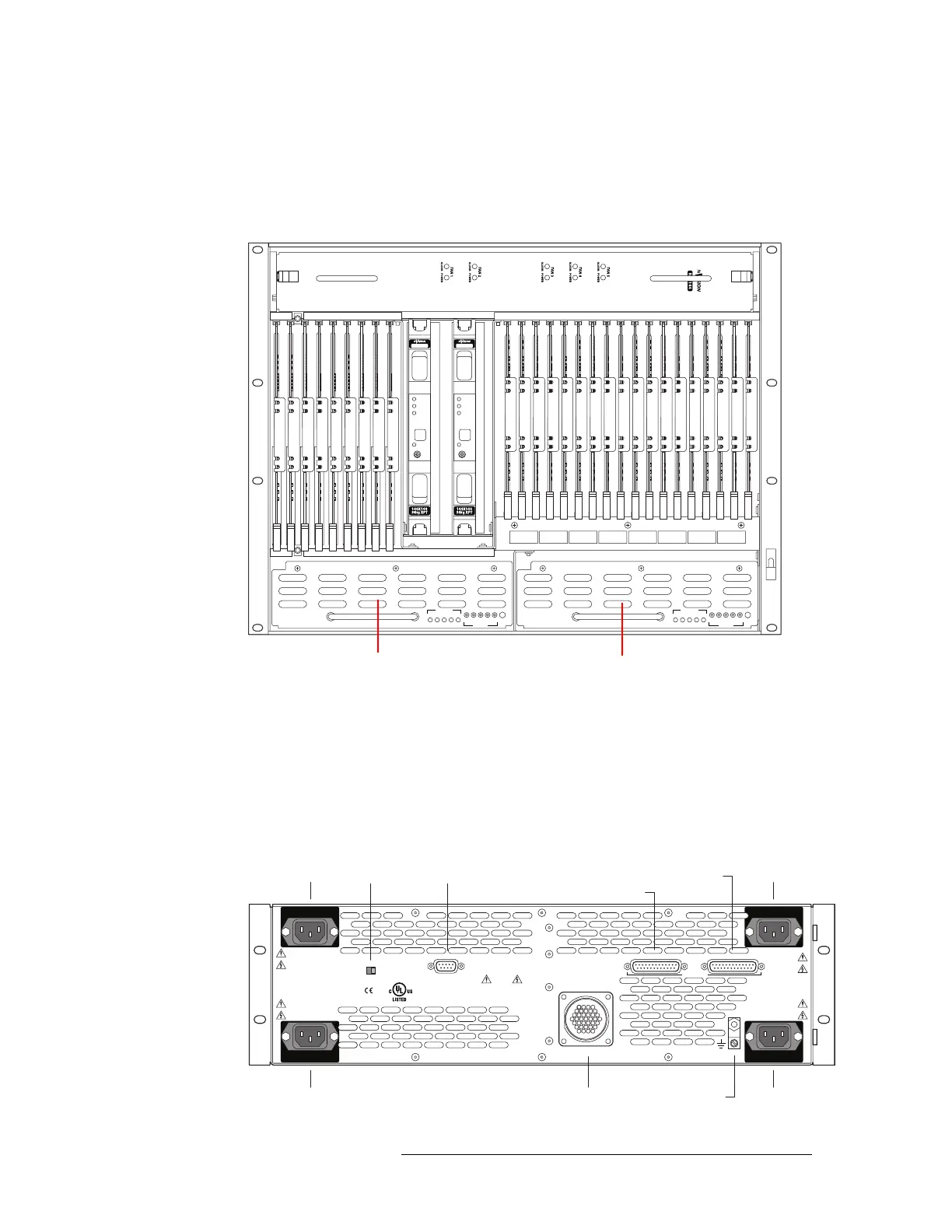
2 Facing the rear of the NV8000 frame, connect one end of a power cable (WC0096) to ‘DC Out-
put’, as shown in Figure 2-33.
Figure 2-33. NV8000 Power Supply (Rear View)
NV8500 NV8500
PS8100
12345
POWER
GND
12345
48V
+
PS8100
12345
POWER
GND
12345
48V
+
1 (primary)
2 (redundant)
PS3
LOWER LEFT
PS1
UPPER LEFT
90-130V~/180-250V~
12.5A/6.25A
50/60Hz
1125 WAT TS
MAX
PS FRAME 1 MONITOR PS FRAME 2 MONITOR
LOOP THRU
90-130V~/180-250V~
12.5A/6.25A
50/60Hz
1125 WAT TS MAX
VIDEO/AUDIO
PROFESSIONAL
CNTRL NO. 9K50
PLEASE READ INSTRUCTION
MANUAL BEFORE CONNECTING
EQUIPMENTTO THE MAINS
E146905
CAUTION
THIS EQUIPMENT HAS FOUR POWER
SUPPLY CORDS. TO REDUCETHE RISK
OF ELECTRIC SHOCK DISCONNECT ALL
POWER SUPPLY CORDS BEFORE SERVICING.
ALARMS
DC OUTPUT POWER
FRAME ID
1 2
PS4
LOWER RIGHT
PS2
UPPER RIGHT
90-130V~/180-250V~
12.5A/6.25A
50/60Hz
1125 WAT TS MAX
90-130V~/180-250V~
12.5A/6.25A
50/60Hz
1125 WAT TS MAX
PS1PS2
PS3PS4
PS Frame 1 Monitor
DC Output Ground Lug
PS Frame 2 MonitorAlarmsFrame ID
 Loading...