24 Rev 2.2 • 27 Mar 10
1. Introduction
Front Module Slots and Rear Connections
Rear Connections
The rear of the NV8500 family router frames (Figure 1-21 on page 28) feature a back plate contain-
ing openings for installing interchangeable backplanes housing connectors. The type and number of
connectors change depending on the signal being managed and which of the NV8500 family rout-
ers are being used.
NV8144
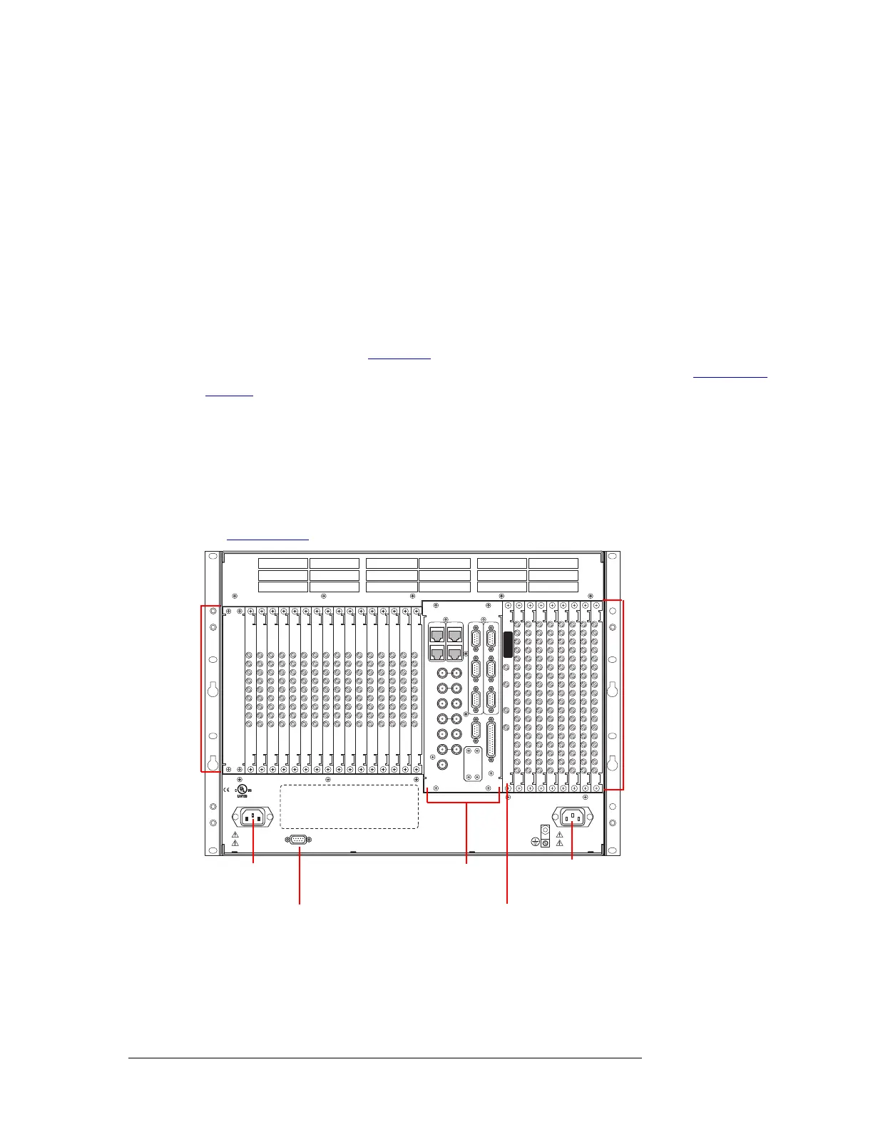
The rear of the NV8144 houses backplanes and system connections. When facing the rear, the far-
thest left-hand section has a blank plate. This corresponds to the control cards, which are installed
through the front of the router frame. Next to the control card plate are 16 backplanes housing con-
nectors for receiving incoming signals. These backplanes are installed in slots that correspond to
active cards for inputs. (See Front Slots
on page 20.) The middle section contains system connec-
tions, such as audio and video references, control systems, and so on. For details, see System Con-
nections on page 32.
To the right of the section containing the system connections is a single backplane for monitor sig-
nals. To the right of the monitor backplane are 8 backplanes housing connectors for distributing
outgoing signals. These backplanes are installed in slots that correspond to active cards for outputs.
At the very top of the frame are grills for exhausting warm air dispersed by the fans in the fan tray.
Near the bottom of the frame are two power connections for connecting the two power supply mod-
ules to power. To the right of the left-most power connection is a connection for alarms. For details,
see System Alarm
on page 36.
Figure 1-19. NV8144 Rear of Router Frame (Rear View)
NV8280 and NV8280-Plus
The rear of the NV8280 and NV8280-Plus house backplanes and system connections, as shown in
Figure 1-20 on page 26. At the very top of the frame are grills for exhausting warm air dispersed by
DIAG (38.4 Kbaud)
CONTROL
IN 1
MONITOR
OUTPUT
IN 2
OUT 2 OUT 1
POWER
SUPPLY
i
MONITORS
TIME CODE
NVISION AUX BUS
RTR EXP OUT
RTR EXP IN
AES REF 1
AES REF 2
VIDEO REF 2
VIDEO REF 1
RTR EXP
10/100 BT
RTR EXP
10/100 BT
CTRL 1
CTRL 2
ALARMS
CTRL 1
CTRL 2
DIAG (38.4 Kbaud)
PRI
SEC
SEC
PRI
90-130V~/180-250V~
12.5A/6.25A
50/60Hz
1125 WATTS MAX
PS1
PS2
90-130V~/180-250V~
12.5A/6.25A
50/60Hz
1125 WATTS MAX
E146905
CNTRL NO. 9K50
PROFESSIONAL
VIDEO/AUDIO
ALARMS
Output
Backplanes
(8)
Input
(16)
Backplanes
System
Connections
Power
Connection
Connection
Power
Alarm
Monitor Backplane
 Loading...