NV8500 family Digital Routers • User’s Guide 83
2. Installation
Making Alarm Connections
Making Alarm Connections
Routers in the NV8500 family provide system alarms that notify you of a malfunction, such as
when a fan or power supply is not functioning properly. Alarms can be connected to an external
alarm indicator that displays visual cues when an alarm is activated. For the router frames that use
the NV8000 power supply frame also has alarm connections. Miranda does not provide external
indicator equipment, but does provide instructions on wiring the alarm connections. See Alarm
Indicator Equipment on page 84.
Both the router frames and the NV8000 power supply send status information to the router control
system. For more information on the alarm connections, see System Alarm
on page 36.
How to Make Alarm Connections for Routers
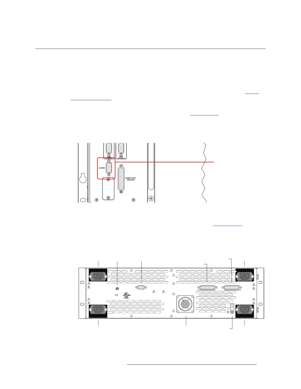
1 On the rear of the router, locate the ‘ALARMS’ connection, as shown in Figure 2-27.
Figure 2-27. System Alarm Connection on Router (Rear View)
2 Connect to the ‘ALARMS’ connection using a DE9 connector and cable.
3 Connect the other end of the cable to an external alarm indicator. See Router Alarms
on page 84
for information on wiring the DE9 connector.
How to Make Alarm Connections for the NV8000
1 On the rear of the NV8000, locate the ‘Alarms’ connection.
Figure 2-28. NV8000 Power Supply (Rear View)
2 Connect to the ‘Alarms’ connection using a DE9 connector and cable.
System Alarm Connector
PS3
LOWER LEFT
PS1
UPPER LEFT
90-130V~/180-250V~
12.5A/6.25A
50/60Hz
1125 WAT TS
MAX
PS FRAME 1 MONITOR PS FRAME 2 MONITOR
LOOP THRU
90-130V~/180-250V~
12.5A/6.25A
50/60Hz
1125 WAT TS MAX
VIDEO/AUDIO
PROFESSIONAL
CNTRL NO. 9K50
PLEASE READ INSTRUCTION
MANUAL BEFORE CONNECTING
EQUIPMENTTO THE MAINS
E146905
CAUTION
THIS EQUIPMENT HAS FOUR POWER
SUPPLY CORDS. TO REDUCETHE RISK
OF ELECTRIC SHOCK DISCONNECT ALL
POWER SUPPLY CORDS BEFORE SERVICING.
ALARMS
DC OUTPUT POWER
FRAME ID
1 2
PS4
LOWER RIGHT
PS2
UPPER RIGHT
90-130V~/180-250V~
12.5A/6.25A
50/60Hz
1125 WAT TS MAX
90-130V~/180-250V~
12.5A/6.25A
50/60Hz
1125 WAT TS MAX
PS1PS2
PS3PS4
PS Frame 1 Monitor
DC Output Ground Lug
PS Frame 2 MonitorAlarmsFrame ID
 Loading...