NV8500 family Digital Routers • User’s Guide 45
1. Introduction
Frame Expansion
Frame Expansion
Two identical NV8500 family expandable router frames (NV8280-Plus or NV8576-Plus) can be
connected to create a switching matrix of up to 1152 inputs and 1152 outputs. The two frames are
linked by connecting expansion connections on one router to expansion connections on a second
router. The expansion connections are:
• I/O Signals
— Each frame has up to 128 signal expansion connectors, each forwarding 9 signals
between two connected routers. Connectors reside on the output expansion backplane. See
Expansion Signal Connections
on page 64.
•Control System
— Only one router frame of the pair is connected directly to the router control
system. Using control system expansion connections, control system connections are required
between the two routers. This enables the control system to see both routers through one control
system connection. See Control System Expansion Connections
on page 73.
• Monitor System
— Only one router frame of the pair is connected directly to the monitoring
equipment. Monitor connections are required between the two routers. This enables the moni-
toring equipment to see both router frames through one monitor connection. See Expansion
Frame Monitor Connections on page 81.
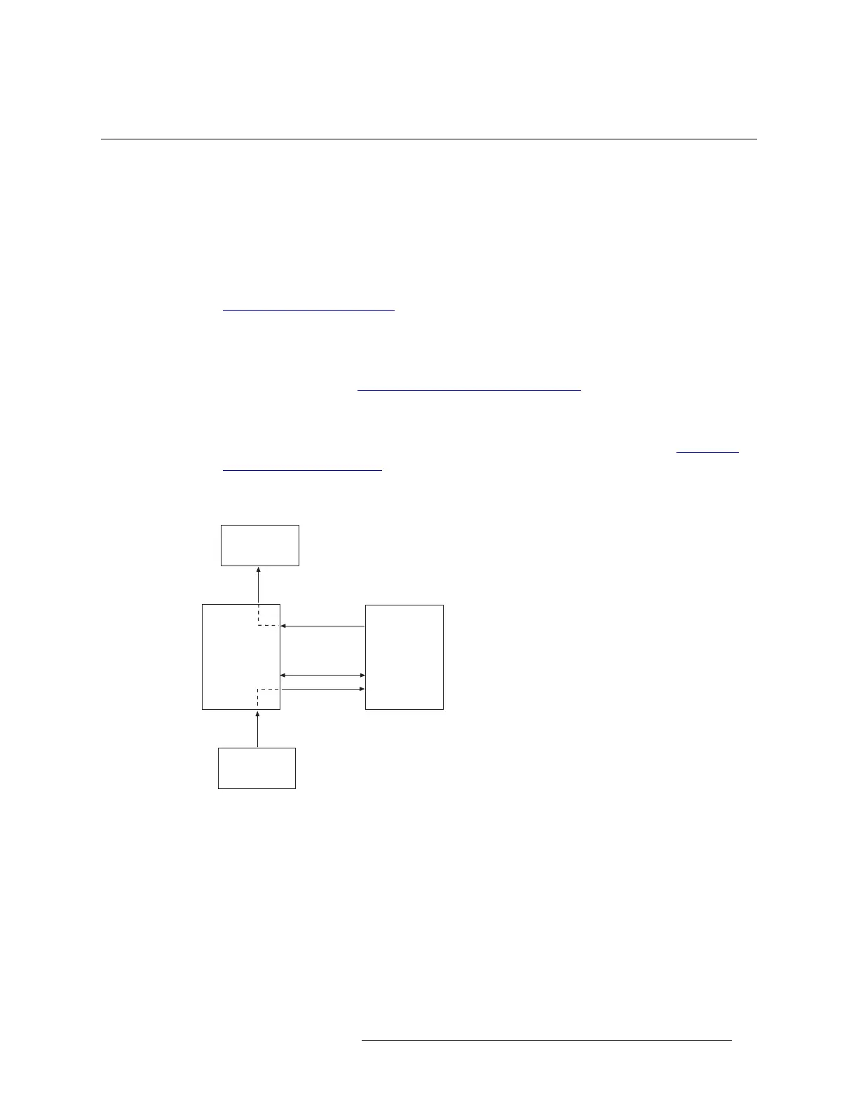
Figure 1-38 shows the flow of signals between two connected router frames. The signals are for-
warded to the connected router through signal expansion connections.
Figure 1-38. Frame Expansion Diagram
Router 1
Expansion
Cables
Router 2
Control
System
Monitoring
Equipment
Monitoring
Signals
Control
 Loading...