NV8500 family Digital Routers • User’s Guide 21
1. Introduction
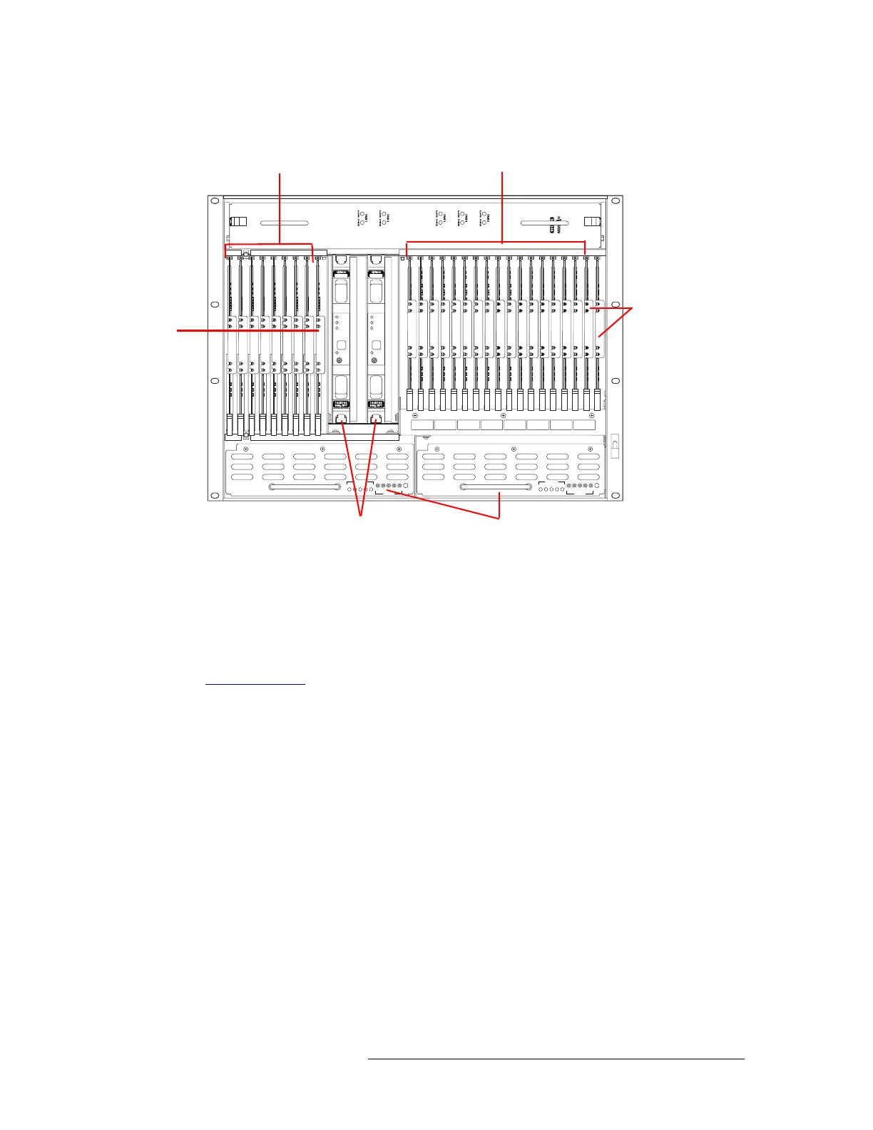
Front Module Slots and Rear Connections
Below the active card slots, at the bottom of the frame, are two power supply modules.
Figure 1-16. NV8144 with Door Removed (Front View)
NV8280 and NV8280-Plus
Figure 1-17 on page 22 shows the front of the NV8280/NV8280-Plus router frame with the door
removed. The NV8280 and the NV8280-Plus have identical frames. What makes an NV8280-Plus
able to connect to another NV8280-Plus frame are the unique expansion output cards and corre-
sponding expansion output backplanes located on the rear of the router. For more information, see
Frame Expansion
on page 45.
From this view, you can see the modules inserted in the slots. At the top of the frame is the fan tray.
Directly below that are 32 slots for output cards. Below the output cards are 32 slots for input cards,
for a total of 64 cards. To the far right of the output card slots are two additional slots for the input
monitor and output monitor cards. Similarly, to the far right of the input card slots are two addi-
tional slots for the primary and secondary control cards.
NV8500 NV8500
PS8100
12345
POWER
GND
12345
48V
+
PS8100
12345
POWER
GND
12345
48V
+
Fan
Output Cards (8)
Monitor
Card
(1)
Input Cards (16)
Control
Cards
(2)
Power Supplies (2)
Crosspoint Cards (2)
 Loading...