NV8500 family Digital Routers • User’s Guide 13
1. Introduction
Signal Rates and Flow
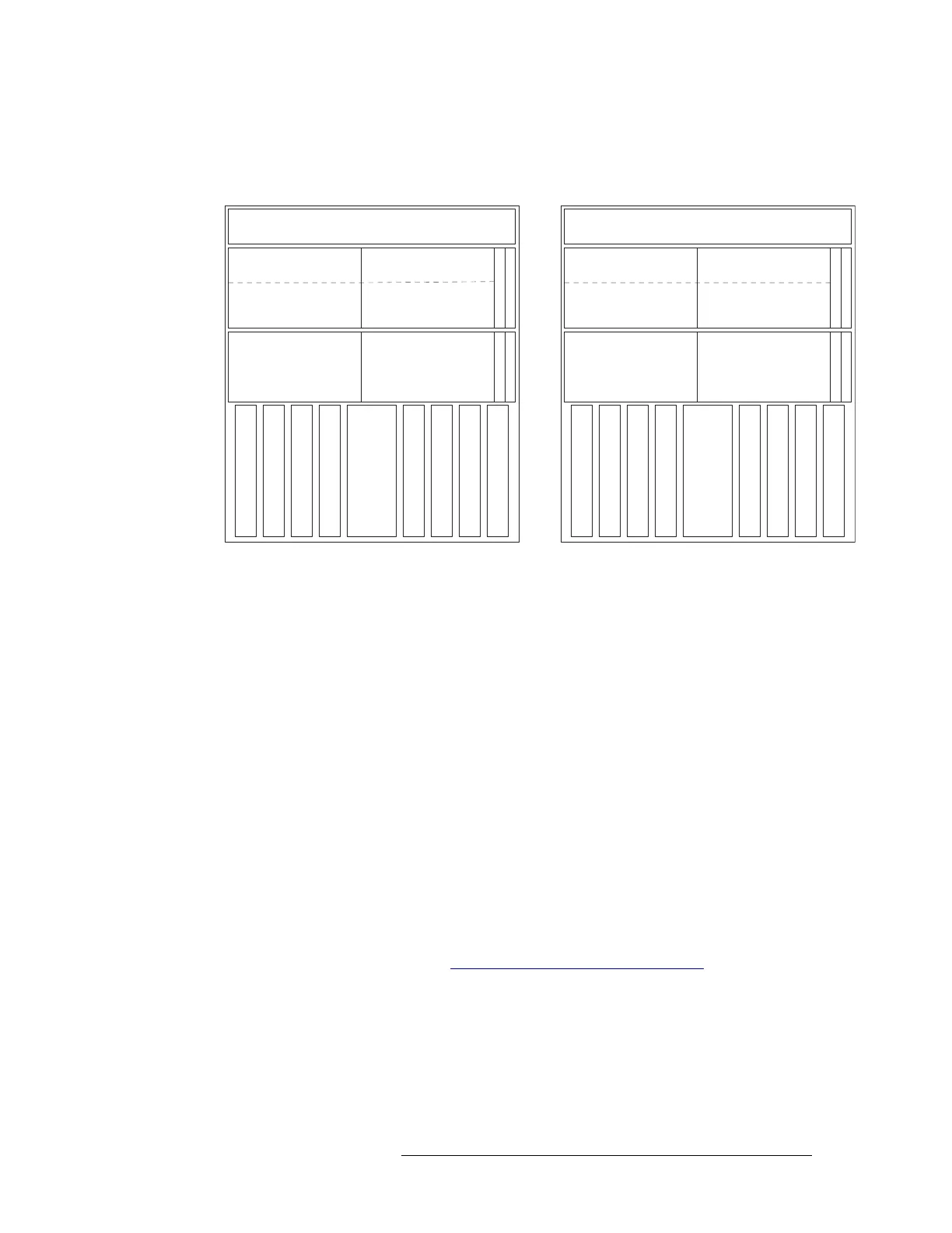
Figure 1-9 shows which signal numbers correspond to which slots when viewing two NV8280-Plus
routers from the front.
Figure 1-9. NV8280-Plus Signals and Corresponding Numbers for Connected Pair (Front View)
Crosspoint Slots and Signals Switched
The crosspoint cards manage signal switching. The crosspoint cards differ depending on the
NV8500 family router frame:
• For the NV8144, NV8280 and NV8280-Plus each card switches up to 144 inputs x 144 outputs.
• For the NV8576 and NV8576-Plus each card switches up to 288 inputs x 288 outputs.
The NV8144 has two slots for crosspoint cards. One is required and one is optional for redundancy.
The redundant crosspoint card takes over switching should the primary crosspoint card fail. All
inputs are sent to both the primary and redundant crosspoint card and switched to any or all outputs
as needed.
The NV8280, NV8280-Plus, NV8576 and NV8576-Plus have 8 slots for 8 crosspoint cards and two
slots for a redundant crosspoint cardset (a single module composed of two joined cards). Depend-
ing on the slot in which it is installed, the crosspoint card switches different signals. Slots are num-
bered 1 through 10, from left to right, when facing the front of the router. The redundant crosspoint
cardset occupies slots 5 and 6. (Refer to Figure 1-5 on page 9 and Figure 1-8 on page 12.)
The optional redundant crosspoint cardset can be installed as a backup for any of the other 8 cross-
point cards. The redundant crosspoint cardset can take over active control from any crosspoint card
installed. For more information, see Setting Redundant Crosspoint Switching
on page 98.
Because the crosspoint cards installed in a specific slot manage specific outputs, depending on your
configuration, you may not need all 8 crosspoint cards. For example, if you are only switching
inputs 1–288 and outputs 1–288 using a stand-alone NV8576 router, crosspoint cards are required
only in slots 1 and 2. The other slots can remain empty.
However, due to router architecture, crosspoint cards must be installed in adjacent pairs to success-
fully route signals: cards must be installed in pairs in slots 1 & 2, slots 3 & 4, slots 5 & 6 or slots 7
FAN
LOCAL OUTPUTS
1144
INPUTS
1144
XPT
(16 cards)
LOCAL OUTPUTS
145288
(16 cards)
(16 cards)
INPUTS
145288
(16 cards)
SEC. CONTROL
PRIM. CONTROL
XPT
XPT
XPT
XPT
XPT
XPT
XPT
REDUNDANT CROSSPOINT
OUTPUTS 289 432
TO OTHER FRAME
OUTPUTS 433576
TO OTHER FRAME
FAN
LOCAL OUTPUTS
289432
INPUTS
289432
INPUT MONITOR
(16 cards)
LOCAL OUTPUTS
433576
(16 cards)
OUTPUT MONITOR
(16 cards)
INPUTS
433576
(16 cards)
SEC. CONTROL
PRIM. CONTROL
REDUNDANT CROSSPOINT
OUTPUTS 1144
TO OTHER FRAME
OUTPUTS 145288
TO OTHER FRAME
(INPUTS 1144)
(OUTPUTS 1144)
(INPUTS 1144)
(OUTPUTS 289432)
(INPUTS 145288)
(OUTPUTS 1144)
(INPUTS 145288)
(OUTPUTS 289432)
(INPUTS 1144)
(OUTPUTS 145288)
(INPUTS 1144)
(OUTPUTS 289576)
(INPUTS 145288)
(OUTPUTS 145288)
(INPUTS 145288)
(OUTPUTS 289576)
XPT
(INPUTS 289432)
(OUTPUTS 289432)
XPT
(INPUTS 289432)
(OUTPUTS 1144)
XPT
(INPUTS 433576)
(OUTPUTS 289432)
XPT
(INPUTS 433576)
(OUTPUTS 1144)
XPT
(INPUTS 289432)
(OUTPUTS 433576)
XPT
(INPUTS 289432)
(OUTPUTS 145288)
XPT
(INPUTS 433576)
(OUTPUTS 433576)
XPT
(INPUTS 433576)
(OUTPUTS 145288)
INPUT MONITOR
OUTPUT MONITOR
Router 1 Router 2