186
5. PARAMETERS
5.4 (E) Environment setting parameters
Life display of the relay contacts of terminals A, B, and C (Pr.507, Pr.508)
• The degree of deterioration of the relay contacts of terminals A1, B1, and C1 is displayed in Pr.507, and that for terminals
A2, B2, and C2 is displayed in Pr.508.
• The number of times the contacts of relay turn ON is counted down from 100% (0 time) by 1% (500 times). When the
counter reaches 10% (45,000 times), bit 6 or bit 7 of Pr.255 turns ON and a warning is output by the Y90 signal.
• Any value can be set in Pr.507 and Pr.508. After replacement of the control circuit terminal block or installation of a control
terminal option, set Pr.507 and Pr.508 again.
5.4.17 Maintenance timer alarm
The Maintenance timer (Y95) signal is output when the inverter's cumulative energization time reaches the time period set with
the parameter. MT1, MT2 or MT3 is displayed on the operation panel.
This can be used as a guideline for the maintenance time of peripheral devices.
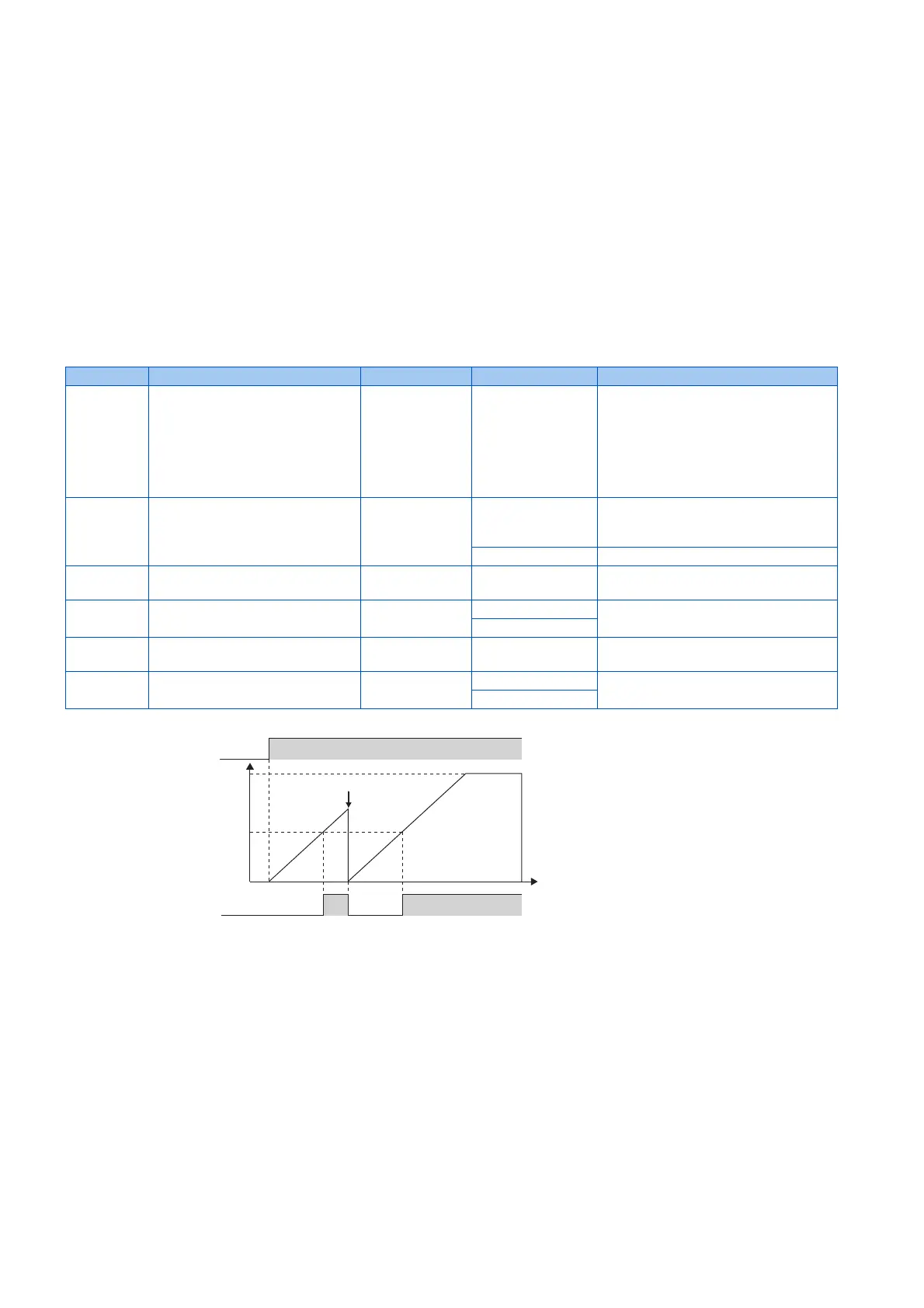
• The cumulative energization time of the inverter is stored in the EEPROM every hour and displayed in Pr.503 (Pr.686,
Pr.688) in 100 h increments. Pr.503 (Pr.686, Pr.688) is clamped at 9998 (999800 h).
• When the value in Pr.503 (Pr.686, Pr.688) reaches the time (100 h increments) set in Pr.504 (Pr.687, Pr.689), the
Maintenance timer (Y95) signal is output, and also MT1, MT2, or MT3 is displayed on the operation panel.
• For the terminal used for Y95 signal output, assign the function by setting "95 (positive logic)" or "195 (negative logic)" in
any of Pr.190 to Pr.196 (Output terminal function selection).
Pr. Name Initial value Setting range Description
503
E710
Maintenance timer 1 0 0 (1 to 9998) Displays the inverter's cumulative
energization time in increments of 100 h
(read-only).
Writing the setting of "0" clears the
cumulative energization time while Pr.503
= "1 to 9998". (Writing is disabled when
Pr.503 = "0".)
504
E711
Maintenance timer 1 warning
output set time
9999 0 to 9998 Set the time until the Maintenance timer
(Y95) signal is output.
MT1 is displayed on the operation panel.
9999 No function
686
E712
Maintenance timer 2 0 0 (1 to 9998) The same function as Pr.503.
687
E713
Maintenance timer 2 warning
output set time
9999 0 to 9998 The same function as Pr.504.
MT2 is displayed on the operation panel.
9999
688
E714
Maintenance timer 3 0 0 (1 to 9998) The same function as Pr.503.
689
E715
Maintenance timer 3 warning
output set time
9999 0 to 9998 The same function as Pr.504.
MT3 is displayed on the operation panel.
9999
First power
Time
ON
Maintenance
timer 1
(Pr. 503)
Set "0" in Pr.503
Y95 signal
MT1 display
OFF ONON
Pr.504
9998
(999800 h)
Operation example of the maintenance timer 1 (Pr.503, Pr.504) (with both MT2 and MT3 OFF)
 Loading...


