415
5. PARAMETERS
5.11 (A) Application parameters
3
4
5
5
5
6
7
8
9
10
5.11.7 PID gain tuning
Changing the PID control manipulated amount and measuring the PID control response enable automatic setting of the
constant optimal for PID control.
For tuning, use the step response method or the limit cycle method.
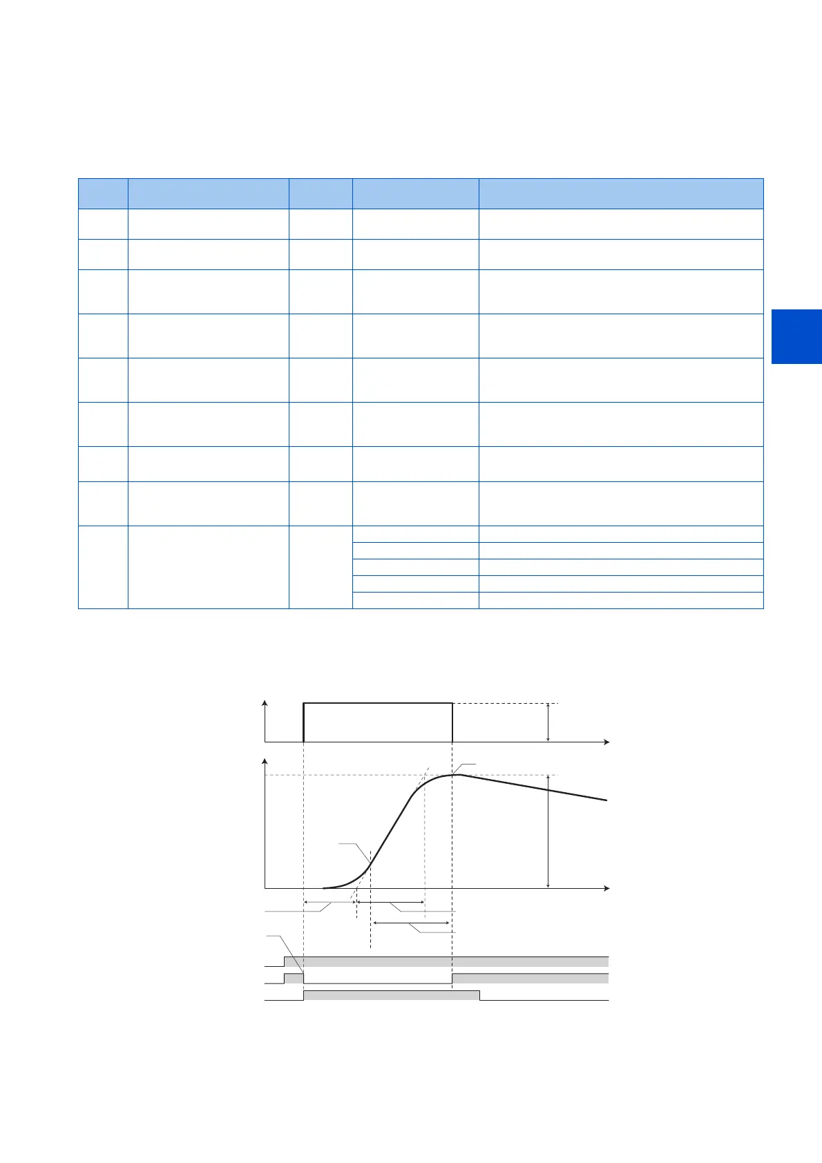
Step response method
• In the step response method, the manipulated amount is changed step by step for the real system. From the change in the
measured values, the maximum slope (R) and the equivalent waste time (L) are calculated to determine each constant.
• The step manipulated amount (Pr.1212 - 1000) is added to the present manipulated amount.
• The measured value is taken for every sampling cycle of step response (Pr.1213). From the variation between the
measured values (Y) and the time (t), the maximum slope (R) is calculated.
Pr. Name Initial
value
Setting range Description
1211
A690
PID gain tuning timeout time 100 s 1 to 9999 s Set the time after the PID gain tuning starts until a
timeout error occurs.
1212
A691
Step manipulated amount 1000% 900 to 1100% Set the step manipulated amount when using the step
response method to perform the PID gain tuning.
1213
A692
Step response sampling
cycle
1 s 0.01 to 600 s Set the cycle for sampling of measurement values when
using the step response method to perform the PID gain
tuning.
1214
A693
Timeout time after the
maximum slope
10 s 1 to 9999 s Set the time after the measurement of the maximum
slope until the completion of the tuning when using the
step response method to perform the PID gain tuning.
1215
A694
Limit cycle output upper
limit
1100% 900 to 1100% Set the upper limit value of the two-position output when
using the limit cycle method to perform the PID gain
tuning.
1216
A695
Limit cycle output lower limit 1000% 900 to 1100% Set the lower limit value of the two-position output when
using the limit cycle method to perform the PID gain
tuning.
1217
A696
Limit cycle hysteresis 1% 0.1 to 10% Set the hysteresis of the set point when using the limit
cycle method to perform the PID gain tuning.
1218
A697
PID gain tuning setting 0 0, 100 to 102, 111, 112,
121, 122, 200 to 202,
211, 212, 221, 222
Select the target loop, method, and control adjustment
method for the PID gain tuning.
1219
A698
PID gain tuning start/status 0 0 PID gain tuning function disabled
1 PID gain tuning start
2 During PID gain tuning (read only)
8 PID gain tuning forced end
9, 90 to 96 Tuning error (read only)
Step manipulated amount
(Pr.1212-1000)
Measured value
variation range Y
Maximum
slope R
(R=Y/T)
Maximum
slope R
(R=Y/T)
Maximum
slope R
(R=Y/T)
Time
Time
Manipulated
amount[%]
Measured value[%]
Equivalent
waste time L (s)
Equivalent time constant T (s)
STF
PID
PGT
Timeout time after the maximum slope (s)
(Pr.1214)
PID gain tuning end
PID gain tuning start
 Loading...


