314
5. PARAMETERS
5.8 (M) Monitor display and monitor output signal
5.8.12 Fault code output selection
When a fault occurs, the corresponding data can be output as a 4-bit digital signal using via an open collector output terminal.
The fault code can be read using an input module of programmable controller, etc.
• Fault codes can be output to the output terminals by setting Pr.76 Fault code output selection = "1 or 2".
• When the setting is "2", a fault code is only output when a fault occurs. In normal operation the terminal outputs the signal
assigned in Pr.191 to Pr.194 (Output terminal function selection).
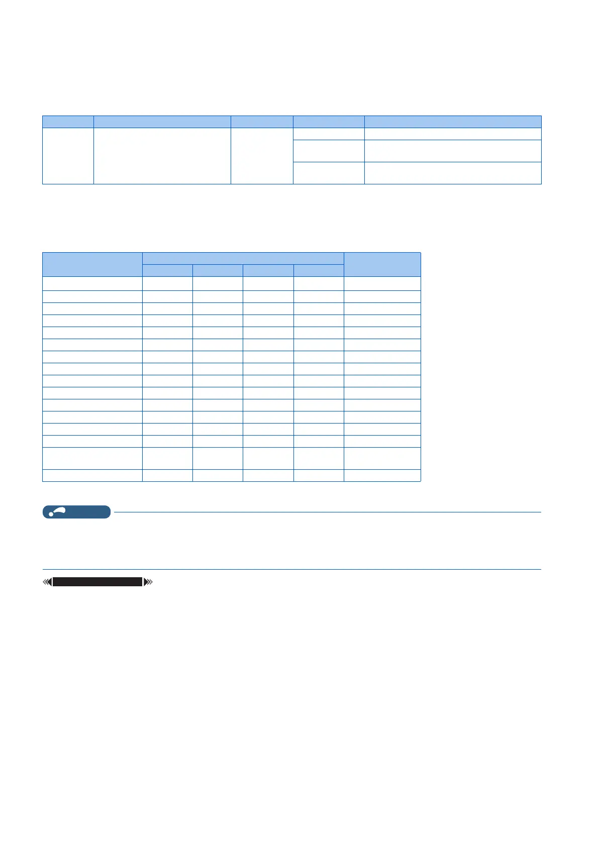
• The fault codes that can be output are shown in the table below. (0: Output transistor OFF, 1: Output transistor ON)
*1 When Pr.76 = "2", the terminal outputs the signal assigned by Pr.191 to Pr.194.
• If an error occurs while Pr.76 ≠ "0", the output terminals SU, IPF, OL, and FU output the signals in the table above
regardless of the settings in Pr.191 to Pr.194 (Output terminal function selection). Take caution when controlling the
inverter with the output signals set by Pr.191 to Pr.194.
Pr.190 to Pr.196 (Output terminal function selection) page 297
Pr. Name Initial value Setting range Description
76
M510
Fault code output selection 0 0 Without fault code output
1 With fault code output
(Refer to the table below.)
2 Fault code is output only when a fault occurs.
(Refer to the table below.)
Fault indication Output terminal operation Fault code
SU IPF OL FU
Normal
*1
00000
E.OC1 00011
E.OC2 00102
E.OC3 00113
E.OV1 to E.OV3 0 1 0 0 4
E.THM 01015
E.THT 01106
E.IPF 0 1 1 1 7
E.UVT 10008
E.FIN 10019
E.BE 1010A
E. GF 1011B
E.OHT 1100C
E.OLT 1101D
E.OPT
E.OP1
1110E
Other than the above 1 1 1 1 F
 Loading...


