33
2. INSTALLATION AND WIRING
2.3 Installation of the inverter and enclosure design
3
2
3
4
5
6
7
8
9
10
High altitude
Use the inverter at an altitude of within 2500 m. For use at an altitude above 1000 m, consider a 3% reduction in the rated
current per 500 m increase in altitude.
If it is used at a higher place, it is likely that thin air will reduce the cooling effect and low air pressure will deteriorate dielectric
strength.
Vibration, impact
The vibration resistance of the inverter is up to 5.9 m/s
2
(2.9 m/s
2
or less for the FR-F860-02890 or higher) at 10 to 55 Hz
frequency and 1 mm amplitude for the directions of X, Y, Z axes. Applying vibration and impacts for a long time may loosen the
structures and cause poor contacts of connectors, even if those vibration and impacts are within the specified values.
Especially when impacts are applied repeatedly, caution must be taken because such impacts may break the installation feet.
Countermeasure
• Provide the enclosure with rubber vibration isolators.
• Strengthen the structure to prevent the enclosure from resonance.
• Install the enclosure away from the sources of the vibration.
2.3.2 Amount of heat generated by the inverter
Regarding the amount of heat generated in the FR-F860 series inverter
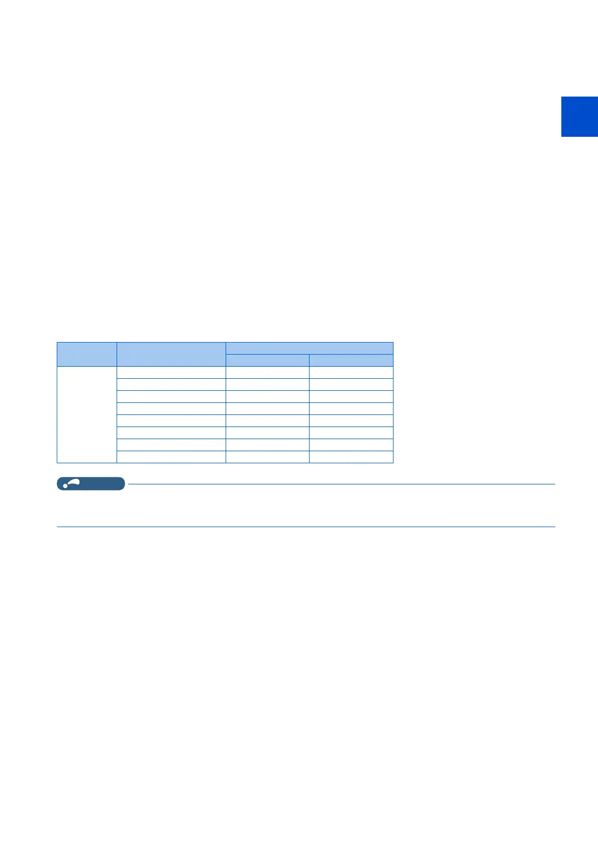
The amount of heat generated by the FR-F860 series inverter is shown in the following tables.
• The amount of heat generated shown assumes that the output current is inverter rated current, power supply voltage is
575 V, and carrier frequency is 2 kHz.
Voltage Inverter model Amount of heat generated (W)
SLD LD
600 V class FR-F860-00680 980 880
FR-F860-01080 1450 1300
FR-F860-01440 2000 1800
FR-F860-01670 2400 2200
FR-F860-02430 3400 3100
FR-F860-02890 3600 3200
FR-F860-03360 4300 3900
FR-F860-04420 5500 5000
 Loading...


