18
1. INTRODUCTION
1.2 Component names
1.2 Component names
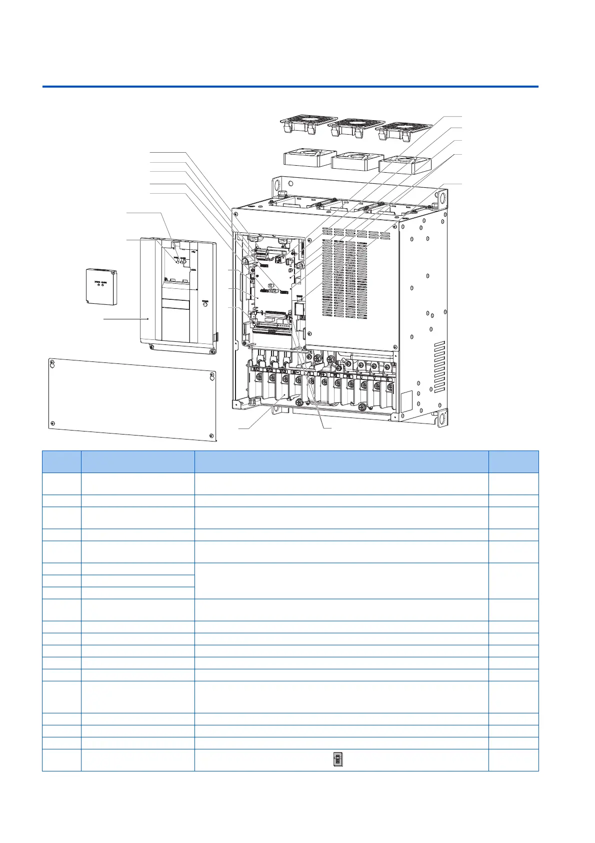
Component names are shown below.
Symbol Name Description Refer to
page
(a) PU connector Connects the operation panel or the parameter unit. This connector also enables
the RS-485 communication.
65
(b) USB A connector Connects a USB memory device. 67
(c) USB mini B connector Connects a personal computer and enables communication with FR
Configurator2.
67
(d) RS-485 terminals Enables RS-485, MODBUS RTU communication and BACnet communication. 68
(e) Terminating resistor selection
switch (SW1)
Select whether or not to use the terminating resistor for RS-485 communication. 68
(f) Plug-in option connector 1 Connects a plug-in option or a communication option. Instruction
Manual of
the option
(g) Plug-in option connector 2
(h) Plug-in option connector 3
(i) Voltage/current input switch
(SW2)
Selects between voltage and current for the terminal 2 and 4 inputs. 318
(j) Control circuit terminal block Connects cables for the control circuit. 50
(k) Main circuit terminal block Connects cables for the main circuit. 41
(l) Charge lamp Stays ON while the power is supplied to the main circuit. 42
(m) Alarm lamp Turns ON when the protective function of the inverter is activated. 42
(n) Power lamp Stays ON while the power is supplied to the control circuit (R1/L11, S1/L21). 42
(o) Front cover (upper side) Remove this cover for the installation of the product, installation of a plug-in
(communication) option, RS-485 terminal wiring, switching of the voltage/current
input switch, etc.
28
(p) Front cover (lower side) Remove this cover for wiring. 28
(q) Accessory cover Remove this cover for using the PU connector. 65
(r) Cooling fan Cools the inverter. (FR-F860-00061 or higher.) 601
(s) Switches for manufacturer
setting (SW3 and SW4)
Do not change the initial setting (OFF ).
─
(q)
(p)
(a)
(j)
(k)
(i)
(k)
(l)
(d)
(h)
(f)
(g)
(m)
(n)
(r)
(o)
(e)
(b)
(c)
(s)
(t)
OFF
ON
 Loading...


