475
5. PARAMETERS
5.12 (N) Operation via communication and its settings
3
4
5
5
5
6
7
8
9
10
• When performing RS-485 communication with multiple inverters, use the RS-485 terminals. (Refer to page 476.)
• Computer-inverter connection cable
Refer to the following for the connection cable (RS-232C RS-485 converter) between the computer with an RS-232C
interface and an inverter. Commercially available products (as of October 2020)
*2 The conversion cable cannot connect multiple inverters. (The computer and inverted are connected in a 1:1 pair.) This is an RS232C-to-RS485
converter-embedded conversion cable. No additional cable or connector is required. For the product details, contact the manufacturer.
• Use Ethernet cables compliant with the following standards when fabricating the cable.
*3 Do not use pins No. 2 and 8 of the communication cable.
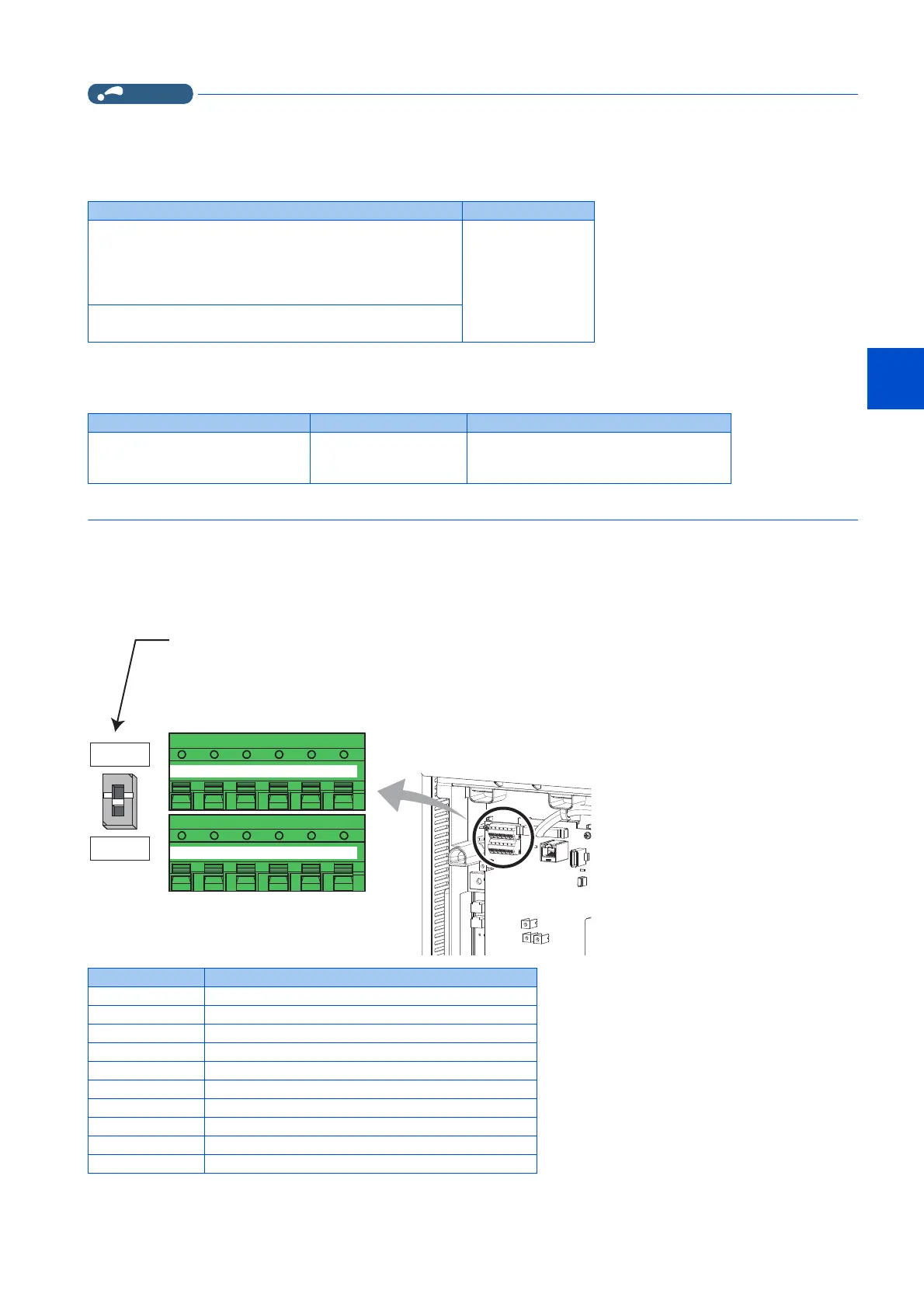
5.12.2 Wiring and configuration of RS-485 terminals
RS-485 terminal layout
Model Manufacturer
Interface embedded cable
DAFXIH-CAB (D-SUB25P for personal computer side)
DAFXIH-CABV (D-SUB9P for personal computer side)
+
Connector conversion cable DINV-485CAB (for inverter side)
*2
Diatrend Corp.
Interface embedded cable dedicated for inverter
DINV-CABV
*2
Ethernet cable Connector Type
Category 5e or higher straight cable
(double shielded / STP)
*3
RJ-45 connector The following conditioning cables:
• IEEE 802.3 (1000BASE-T)
• ANSI/TIA/EIA-568-B (Category 5e)
Name Description
RDA1 (RXD1+) Inverter receive +
RDB1 (RXD1-) Inverter receive -
RDA2 (RXD2+) Inverter receive + (for branch)
RDB2 (RXD2-) Inverter receive - (for branch)
SDA1 (TXD1+) Inverter send +
SDB1 (TXD1-) Inverter send -
SDA2 (TXD2+) Inverter send + (for branch)
SDB2 (TXD2-) Inverter send - (for branch)
P5S (VCC) 5V Permissible load current 100 mA
SG (GND) Earthing (grounding) (connected to terminal SD)
Terminating resistor switch
Initially-set to "OPEN".
Set only the terminating resistor switch of
the remotest inverter to the "100Ω" position.
OPEN
100Ω
+-+
TXD RXD
-
VCC GND
+-+
TXD RXD
-
VCC GND
RDA1
(RXD1+)
RDB1
(RXD1-)
RDA2
(RXD2+)
RDB2
(RXD2-)
SDA1
(TXD1+)
SDB1
(TXD1-)
SDA2
(TXD2+)
SDB2
(TXD2-)
P5S
(VCC)
SG
(GND)
P5S
(VCC)
SG
(GND)
 Loading...


