240
5. PARAMETERS
5.7 (H) Protective function parameter
5.7.4 Initiating a protective function
A fault (protective function) is initiated by setting the parameter.
This function can be used to check how the system operates at activation of a protective function.
• To initiate a fault (protective function), set the assigned number of the protective function you want to initiate in Pr.997.
• The value set in Pr.997 is not stored in EEPROM.
• When a protective function activates, the inverter trips, a fault is displayed, and a fault signal (ALM, ALM2) is output.
• The latest fault in the fault history is displayed while the fault initiation function is in operation. After a reset, the fault history
goes back to the previous status. (The protective function generated by the fault is not saved in the fault history.)
• Perform inverter reset to cancel the protective function.
• For the selectable parameter by Pr.997 and the corresponding protective functions, refer to page 570.
• If a protective function is already operating, no fault can be activated by Pr.997.
• The retry function is disabled when a protective function has been initiated by the fault initiation function.
• If a fault occurs after a protective function has been activated, the protective function indication does not change. The fault
is not saved in the fault history either.
5.7.5 Output short-circuit fault
Select the reset operation and fault indication for an output short-circuit.
• The fault indication for an output short-circuit (E.OC1 to E.OC3, and E.SCF) can be changed by the Pr.521 setting.
• When an output short-circuit is detected while Pr.521 = "1", E.SCF is displayed and the inverter output is shut off. (Refer
to page 576)
• When E.SCF occurs while Pr.521 = "1", E.SCF can be reset only by turning OFF the control circuit power. (E.OC1 to E.OC3
can be reset by any reset method.)
• This restriction prevents the inverter from being damaged due to repeated reset operations by the other methods such as
entering the RES signal.
• When E.SCF occurs, the output short-circuit detection (ALM4) signal can be output.
• For the terminal used to output the ALM4 signal, set "23" (positive logic) or "123" (negative logic) in any of Pr.190 to Pr.196
(Output terminal function selection).
• If the automatic bypass switching after inverter fault is enabled (Pr.138 is set to "1"), the operation is not switched to the
commercial power supply operation even when E.SCF occurs.
• When short-circuit resistance is large, the current does not reach the short-circuit detection level. In such a case, an output
short-circuit cannot be detected.
• Changing the terminal assignment using Pr.190 to Pr.196 (Output terminal function selection) may affect the other
functions. Set parameters after confirming the function of each terminal.
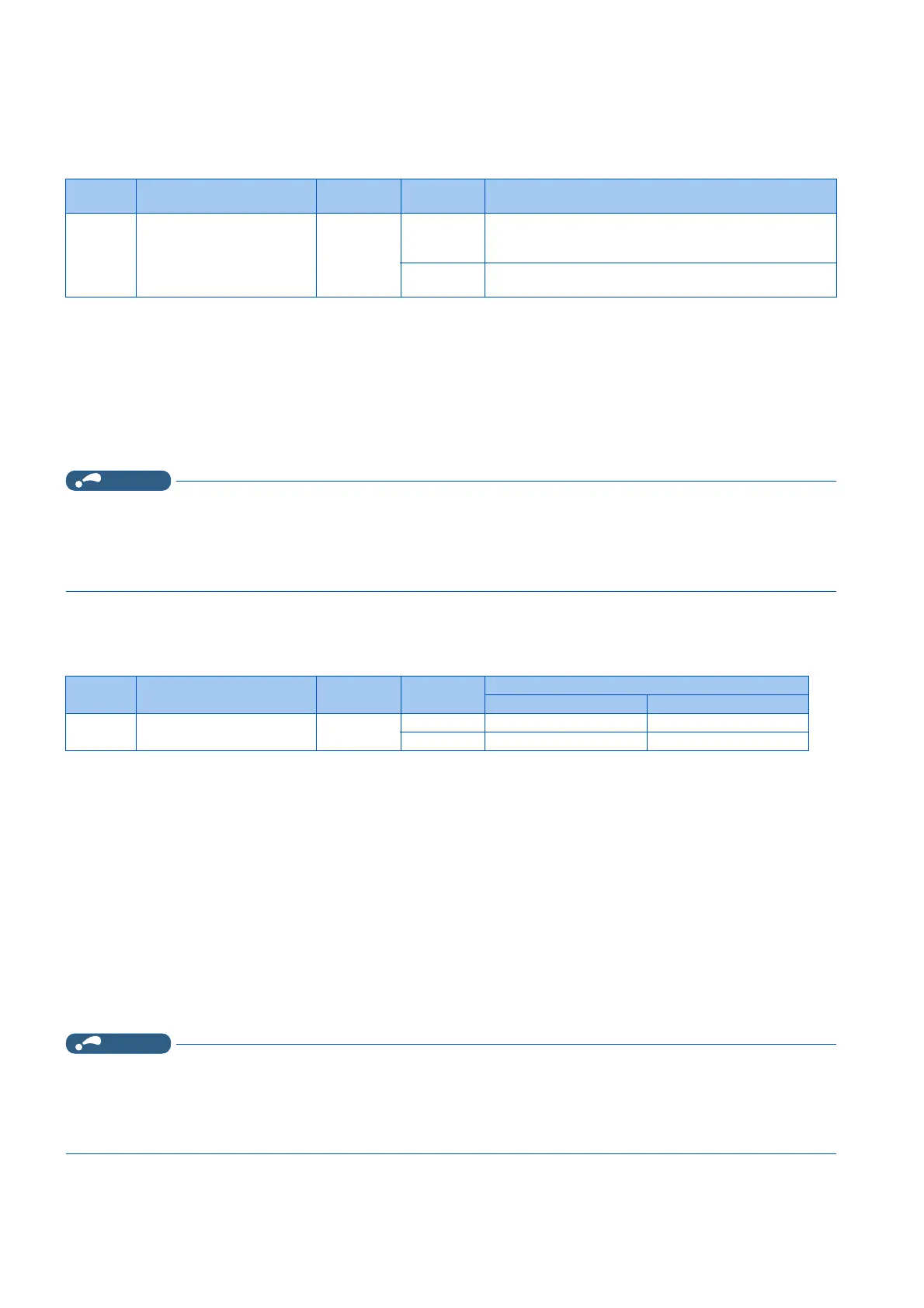
Pr. Name Initial value Setting
range
Description
997
H103
Fault initiation 9999 16 to 253 The setting range is same with the one for fault data codes of
the inverter (which can be read through communication).
Written data is not stored in EEPROM.
9999 The read value is always "9999".
With this setting, the protective function does not activate.
Pr. Name Initial value Setting
range
Description
Operation after detection Reset method
521
H194
Output short-circuit
detection
0 0 E.OC1 to E.OC3 Not restricted
1 E.SCF Restricted
 Loading...


