473
5. PARAMETERS
5.12 (N) Operation via communication and its settings
3
4
5
5
5
6
7
8
9
10
5.12 (N) Operation via communication and its settings
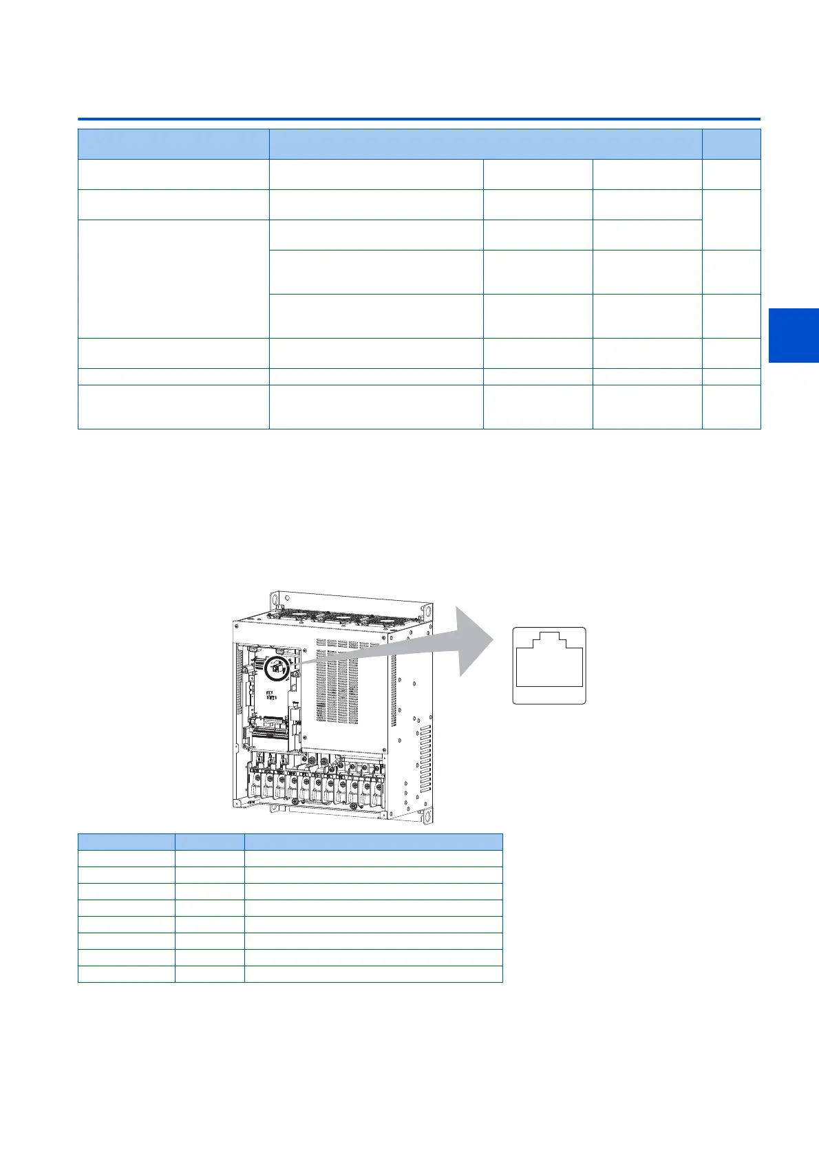
5.12.1 Wiring and configuration of PU connector
Using the PU connector enables communication operation from a personal computer, etc.
When the PU connector is connected with a personal, FA or other computer by a communication cable, a user program can
run and monitor the inverter or read and write to parameters.
PU connector pin-outs
Purpose Parameter to set Refer to
page
To start operation via
communication
Initial setting of operation via
communication
P.N000, P.N001,
P.N013, P.N014
Pr.549, Pr.342,
Pr.502, Pr.779
478
To operate via communication
from PU connector
Initial setting of computer link
communication (PU connector)
P.N020 to P.N028 Pr.117 to Pr.124 483
To operate via communication
from RS-485 terminals
Initial setting of computer link
communication (RS-485 terminals)
P.N030 to P.N038 Pr.331 to Pr.337,
Pr.341
MODBUS RTU communication
specification
P.N002, P.N030,
P.N031, P.N033,
P.N034, P.N080
Pr.539, Pr.331 to
Pr.334, Pr.343
500
BACnet MS/TP protocol P.N030, P.N031,
P.N050 to P.N054
Pr.331, Pr.332,
Pr.390, Pr.726 to
Pr.729
516
To Communicate using USB (FR
Configurator2)
USB communication P.N040, P.N041 Pr.547, Pr.548 532
To connect a GOT GOT automatic recognition P.N020, P.N030 Pr.117, Pr.331 533
To back up the data of parameter
settings and PLC function to the
GOT
Backup/restore P.N110, P.N111 Pr.434, Pr.435 535
Pin number Name Description
1 SG Earth (ground) (connected to terminal 5)
2 ― Operation panel power supply
3 RDA Inverter receive+
4 SDB Inverter send-
5 SDA Inverter send+
6 RDB Inverter receive-
7 SG Earth (ground) (connected to terminal 5)
8 ― Operation panel power supply
Inverter
(Receptacle side)
Front view
81to
 Loading...


