599
7. PRECAUTIONS FOR MAINTENANCE AND INSPECTION
7.1 Inspection item
3
4
5
5
5
5
7
8
9
10
7.1.4 Checking the inverter module and the converter module
Preparation
• Disconnect the external power supply cables (R/L1, S/L2, T/L3) and motor cables (U, V, W).
• Prepare a continuity tester. (For the resistance measurement, use the 100 Ω range.)
Checking method
Change the polarity of the tester alternately at the inverter terminals R/L1, S/L2, T/L3, U, V, W, P/+, and N/- and check the
electric continuity.
NOTE
• Before measurement, check that the smoothing capacitor is discharged.
• At the time of electric discontinuity, the measured value is almost . When there is an instantaneous electric continuity,
due to the smoothing capacitor, the tester may not indicate . At the time of electric continuity, the measured value is
several Ω to several tens of Ω. When all measured values are almost the same (although values may not be constant
depending on the tester type), it shows that there are no electrical paths with problems.
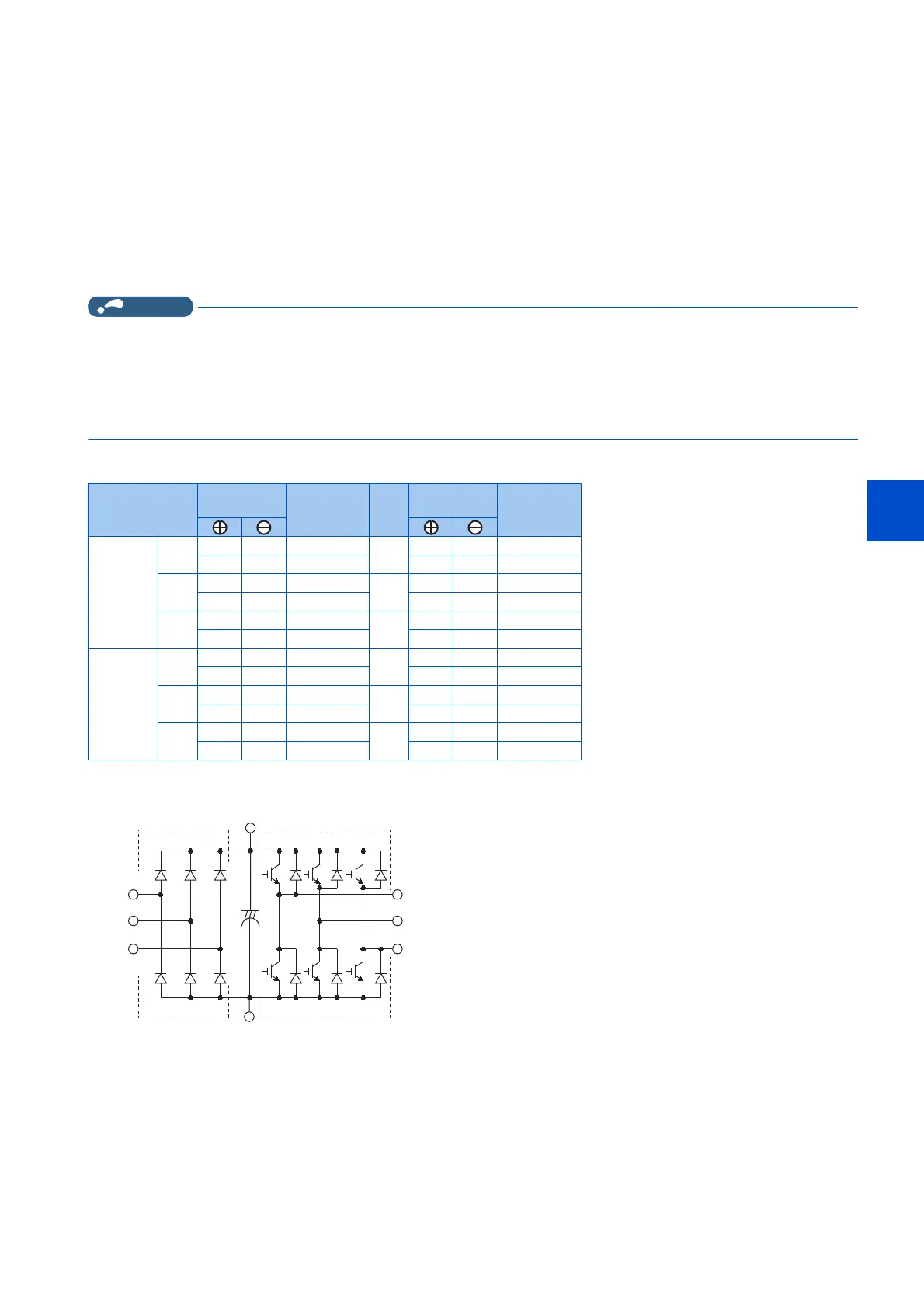
Module device numbers and terminals to be checked
(Assuming that an analog meter is used.)
Tester
polarity
Result Tester
polarity
Result
Converter
module
D1 R/L1 P/+ Discontinuity D4 R/L1 N/- Continuity
P/+ R/L1 Continuity N/- R/L1 Discontinuity
D2 S/L2 P/+ Discontinuity D5 S/L2 N/- Continuity
P/+ S/L2 Continuity N/- S/L2 Discontinuity
D3 T/L3 P/+ Discontinuity D6 T/L3 N/- Continuity
P/+ T/L3 Continuity N/- T/L3 Discontinuity
Inverter
module
TR1 U P/+ Discontinuity TR4 U N/- Continuity
P/+ U Continuity N/- U Discontinuity
TR3 V P/+ Discontinuity TR6 V N/- Continuity
P/+ V Continuity N/- V Discontinuity
TR5 W P/+ Discontinuity TR2 W N/- Continuity
P/+ W Continuity N/- W Discontinuity
Converter module Inverter module
D1 D2 D3
D4 D5 D6
TR1 TR3 TR5
TR4 TR6 TR2
U
V
W
R/L1
S/L2
T/L3
C
P/+
N/−
 Loading...


