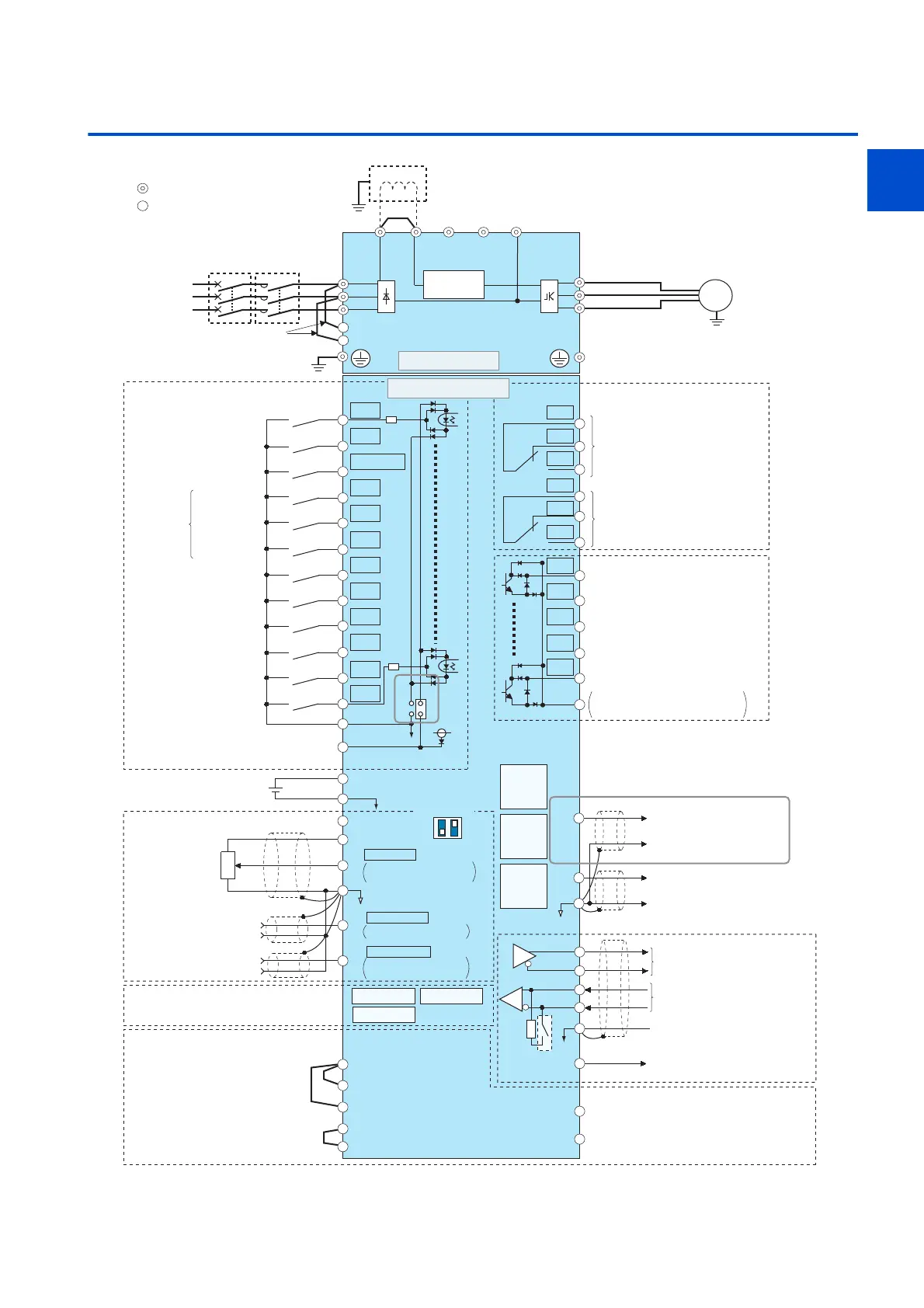
2. INSTALLATION AND WIRING
Three-phase
AC power
supply
MCCB
R/L1
S/L2
T/L3
R1/L11
S1/L21
PC
24VDC power supply
(Common for external power supply transistor)
Forward rotation start
Reverse rotation start
Start self-holding selection
Middle speed
High speed
Low speed
Jog operation
Second function selection
Output stop
Reset
Terminal 4 input selection
(Current input selection)
Frequency setting signals (Analog)
10E(+10V)
10(+5V)
2
(Analog common)
2
3
1
Auxiliary
input
Terminal 4 input
(Current input)
1
4
Frequency setting
potentiometer
1/2W1kΩ
Running
Up to frequency
Instantaneous
power failure
Overload
Frequency detection
Open collector output common
Sink/source common
Control input signals
(No voltage input allowed)
Jumper
Motor
Relay output 1
(Fault output)
C1
B1
A1
U
V
W
P1
Earth
(Ground)
0 to ±5VDC selectable
0 to ±10VDC
Multi-speed
selection
Open collector output
Contact input common
Earth
(Ground)
Main circuit terminal
Control circuit terminal
0 to 5VDC
0 to 10VDC
selectable
MC
Main circuit
C2
B2
A2
Relay output 2
Relay output
M
0 to 20mADC
0 to 5VDC
0 to 10VDC
selectable
4 to 20mADC
TXD+
Terminating
resistor
TXD-
RXD+
RXD-
GND
(SG)
Data
transmission
GND
RS-485 terminals
PU
connector
USB A
connector
USB
mini B
connector
SINK
SOURCE
Connector for plug-in option connection
STF
STR
STP(STOP)
RH
RM
RL
JOG
RT
MRS
RES
AU
CS
SD
RUN
SU
IPF
OL
FU
SE
Data
reception
(+)
(-)
5
+24
24V external power
supply input
SD
Common terminal
VCC
(+)
(-)
5V
(Permissible load current 100mA)
Sink logic
Earth (Ground)
Connector 1 Connector 2
Connector 3
Jumper
PR N/-P/+
Control circuit
Initial value
Initial value
Initial value
ON
4
2
OFF
Voltage/current
input switch
DC reactor
So (SO)
SOC
S1
S2
PC
SD
SIC
For manufacturer
Shorting
wire
P3
Analog current output
(0 to 20mADC)
F/C
(CA)
(-)
(+)
(-)
(+)
Analog signal output
AM
5
(0 to ±10VDC)
24V
Inrush current
limit circuit
 Loading...


