Chapter 4 Installation Gen 3 Site Controller System Manual
Intercabling Connections
4-42 68P80801E30-A 5/1/2002
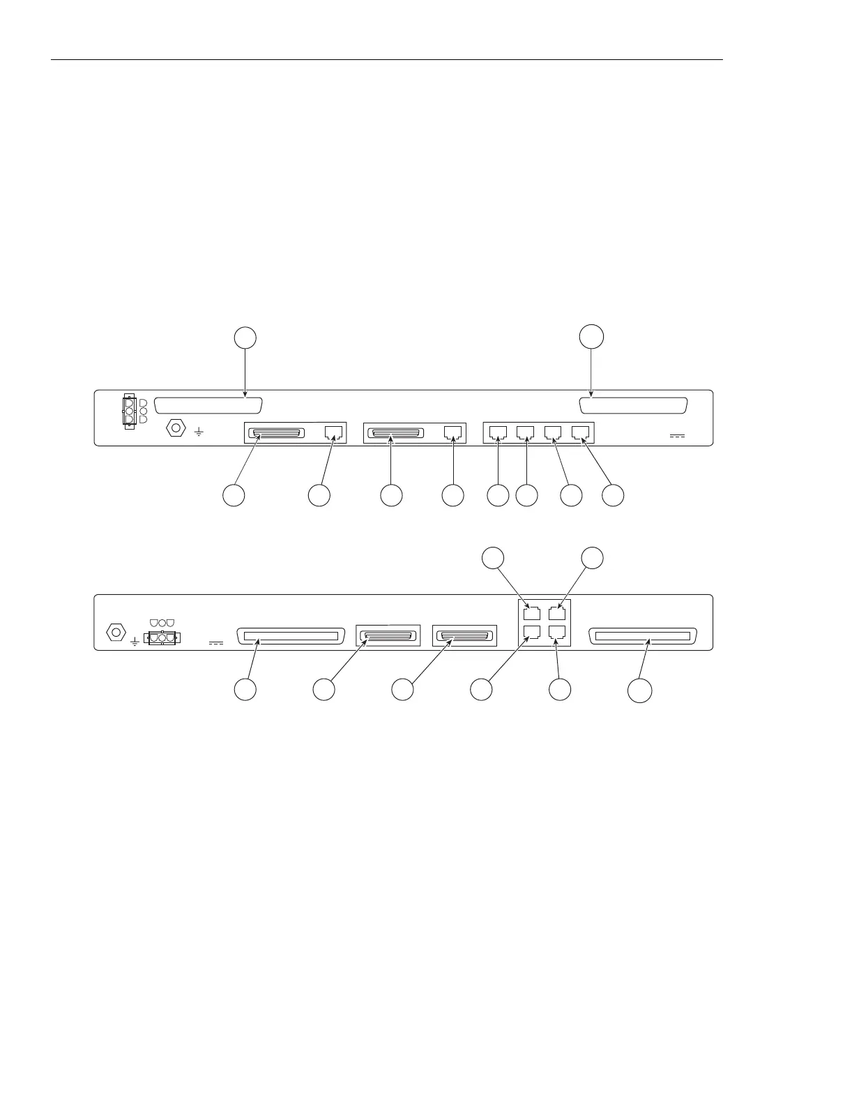
EAS/EAS2 rear panel connectors appear in Figure 4-20. User and system
alarm / control circuits connect to respective 50-pin connectors: Notice
connectors P9 (USER ALARM CONTROL) and P10 (SYSTEM ALARM /
CONTROL). Various system (internal) alarm circuits interface to the EAS/
EAS2 via connectors P5 through P8.
Five sets of changeover relay contacts allow control of external equipment.
The relays are rated 50 Vdc at 250 mA. (If switching requirements exceed
these ratings, use a relay contact to actuate a power relay.)
RF#3
iSC411
042202JNM
RF#2RF#1CONTROLSERIALPARALLEL
CONTROLLER B
SERIALPARALLEL
CONTROLLER A
RTN
-48V
USER ALARM/CONTROL
SYSTEM ALARM/CONTROL
P10
P9
P1 P2 P3 P4 P5 P6 P8P7
ENVIRONMENTAL ALARM SYSTEM
Motorola
-48V , 1.0A
RF3
RF2
RF1CONTROL
-48V
MOTOROLA
ENVIRONMENTAL
ALARM SYSTEM
INPUT:
PARALLEL
CONTROLLER B
PARALLEL
CONTROLLER A
USER ALARM/CONTROL
RTN
SYSTEM ALARM/CONTROL
-48V , 0.5A
P1 P3 P7 P8
P6P5
P9
P10
Figure 4-20 EAS/EAS2 rear panel connectors
EAS
EAS2
 Loading...


