Chapter 3 Pre-Installation Gen 3 Site Controller System Manual
Alarm Wiring
3-26 68P80801E30-A 5/1/2002
Punch Block 1 - Alarm Connections
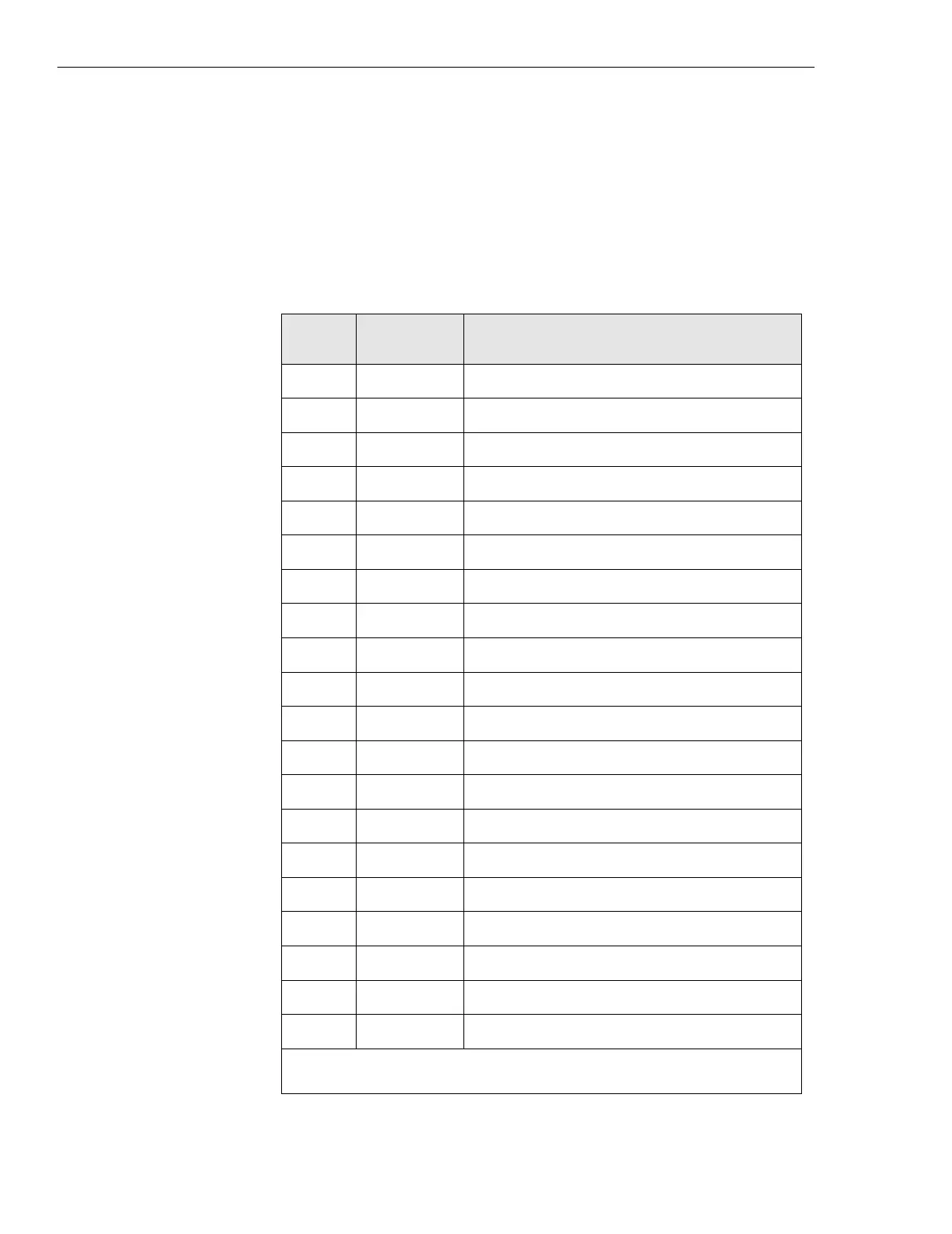
The EAS/EAS2 connector and pin label information refers to the connectors
on the EAS/EAS2 itself. Only the alarm code number is passed to the OMC.
Table 3-6 shows those alarms that connect from the System/Alarm/Control
connector on the back of the EAS/EAS2 to punch block 1.
Table 3-6 Punch block 1 pin-outs
Alarm
code
Punch block
pairs
EAS/EAS2 standard alarm connection
210 23, 48 reserved for system use
219 7, 32 predefined input, site entry
220 8, 33 predefined input, site high ambient temperature
221 9, 34 predefined input, site low ambient temperature
222 10, 35 predefined input, site smoke detector
223 11, 36 predefined input, site AC surge protector
224 22, 47 reserved for system use
241 21, 46 reserved for system use
242 12, 37 AC Power failure
243 13, 38 low DC voltage
244 14, 39 high DC voltage
245 15,40 breaker failure alarm
246 16, 41 minor rectifier module failure
247 17, 42 major rectifier failure
248* 30, 6, 5 pre-defined output generator remote start
249 20, 45 reserved for system use
250 19, 44 reserved for system use
251 18, 43 reserved for system use
253* 26, 2, 1 customer defined output
254* 28, 4, 3 customer defined output
* These alarms are outputs controlled by the EAS/EAS2 and/or OMC.
 Loading...


