Chapter 3 Pre-Installation Gen 3 Site Controller System Manual
Site Planning
3-4 68P80801E30-A 5/1/2002
■ The site floor should be level to within 1/8” and able to support the weight
of site equipment.
Rack Configurations
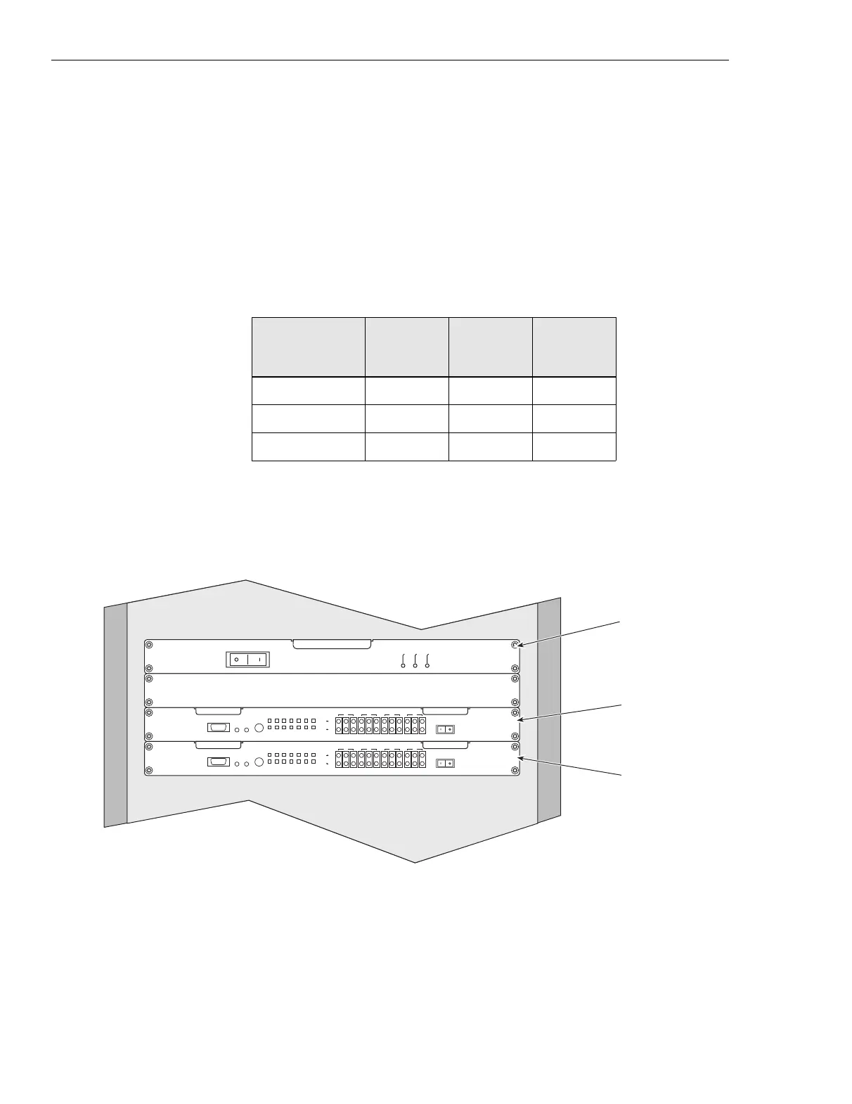
Table 3-1 lists the dimensions for the Controller and EAS/EAS2. Figure 3-1
shows the racking arrangement for the Controller and EAS/EAS2.
Table 3-1 Controller and EAS/EAS2 dimensions
Equipment Chassis
Width
(inches)
Depth
(inches)
Height
(inches)
Controller 17 9 1.75
EAS 17 15 1.75
EAS2 17 9 1.75
Input
Active
Output
Active
Power
On
POWER
EqpMonNet
1
EqpMonNet
2
EqpMonNet
3
EqpMonNet
4
Net Eqp
Net Eqp
1234
GPS
Active
Power
LOS/
Yellow
AIS
FE/CRC
BPV/PD
Net
Local
Mon
Abort/
Reset
Sel/
Loop
Service Access
DCE
Power
OOF
EqpMonNet
1
EqpMonNet
2
EqpMonNet
3
EqpMonNet
4
Net Eqp
Net Eqp
1234
GPS
LOS/
Yellow
AIS
FE/CRC
BPV/PD
Net
Local
Mon
Abort/
Reset
Sel/
Loop
Service Access
DCE
Power
OOF
EAS
OR
EAS2
iSC A
iSC096
010802JNM
iSC B
Figure 3-1 Typical site controller racking arrangement
 Loading...


