Chapter 3 Pre-Installation Gen 3 Site Controller System Manual
Alarm Wiring
3-28 68P80801E30-A 5/1/2002
Punch Block 2 – Alarm Connections
The EAS/EAS2 connector and pin label information refers to the connectors
on the EAS/EAS2 itself. Only the alarm code number is passed to the OMC.
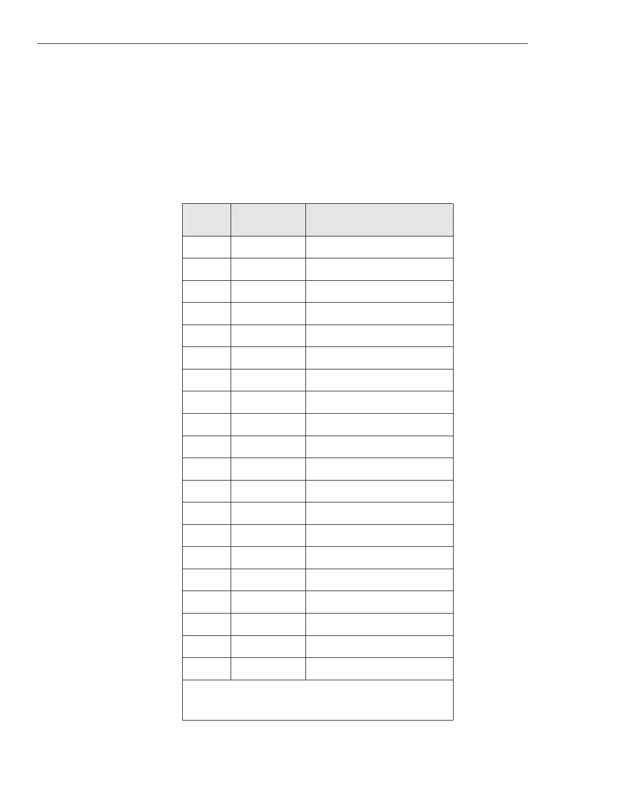
Table 3-7 shows those alarms that connect from the User Alarm/Control
connector on the back of the EAS/EAS2 to punch block 2.
Table 3-7 Punch block 2 pin-outs
Alarm
code
Punch block
pairs
EAS/EAS2 standard alarm
connection
201 6, 31 customer defined input
202 5, 30 customer defined input
203 14, 39 customer defined input
204 13, 38 customer defined input
205 12, 37 customer defined input
206 11, 36 customer defined input
207 10, 35 customer defined input
208 9, 34 customer defined input
209 8, 33 customer defined input
211 7, 32 customer defined input
212 22, 47 customer defined input
213 21, 46 customer defined input
214 20, 45 customer defined input
215 19, 44 customer defined input
216 18, 43 customer defined input
217 17, 42 customer defined input
218 16, 41 customer defined input
252 15, 40 customer defined input
255* 26, 2, 1 customer defined output
256* 28, 4, 3 customer defined output
* These alarms are outputs controlled by the EAS/EAS2 and/or
OMC.
 Loading...


