68P80801E30-A 5/1/2002 10-5
Gen 3 Site Controller System Manual Chapter 10 Environmental Alarm System
EAS Functional Description
Connectors
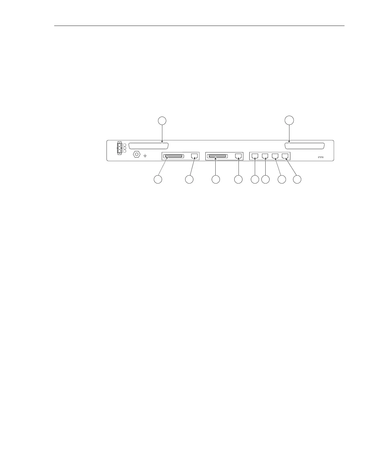
Figure 10-3 shows the rear view of the EAS. Table 10-3 lists and describes
the EAS connectors.
RF#3
iSC411
103100JNM
RF#2RF#1CONTROLSERIALPARALLEL
CONTROLLER B
SERIALPARALLEL
CONTROLLER A
RTN
-48V
USER ALARM/CONTROL
SYSTEM ALARM/CONTROL
P10
P9
P1 P2 P3 P4 P5 P6 P8P7
ENVIRONMENTAL ALARM SYSTEM
Motorola
-48V , 1.0A
Figure 10-3 EAS (rear view)
 Loading...


