68P80801E30-A 5/1/2002 4-47
Gen 3 Site Controller System Manual Chapter 4 Installation
Intercabling Connections
EAS/EAS2 Connector Pinouts
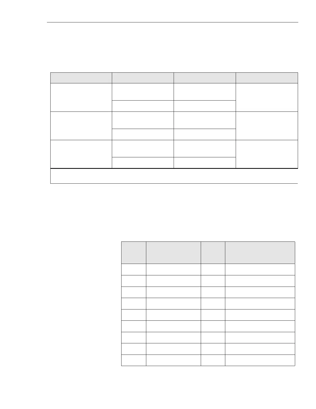
EAS/EAS2 connectors and punch block information appear in Table 4-23.
Only the alarm code number is passed to the OMC. The alarm code is the
software message relating the punch block pins with the alarm.
Table 4-22 Internal Relay Outputs
Alarm Code Contact P5 (CONTROL) Pin No. Function
238 NO 3 output, RF Relay Cabinet
1
COM 4
239 NO 5 output, RF Relay Cabinet
2
COM 6
240 NO 7 output, RF Relay Cabinet
3
COM 8
NOTE:
NO = Normally Open.
Table 4-23 Punch block pinouts
Alarm
code
EAS/EAS2
connector
Punch
block
pairs
EAS/EAS2 standard
alarm connection
201 User Alarm/Control 6, 31 customer defined input
202 User Alarm/Control 5, 30 customer defined input
203 User Alarm/Control 14, 39 customer defined input
204 User Alarm/Control 13, 38 customer defined input
205 User Alarm/Control 12, 37 customer defined input
206 User Alarm/Control 11, 36 customer defined input
207 User Alarm/Control 10, 35 customer defined input
208 User Alarm/Control 9, 34 customer defined input
209 User Alarm/Control 8, 33 customer defined input
 Loading...


