68P80801E30-A 5/1/2002 C-7
Gen 3 Site Controller System Manual Appendix C Cabling Diagrams
Site Controller Cabling
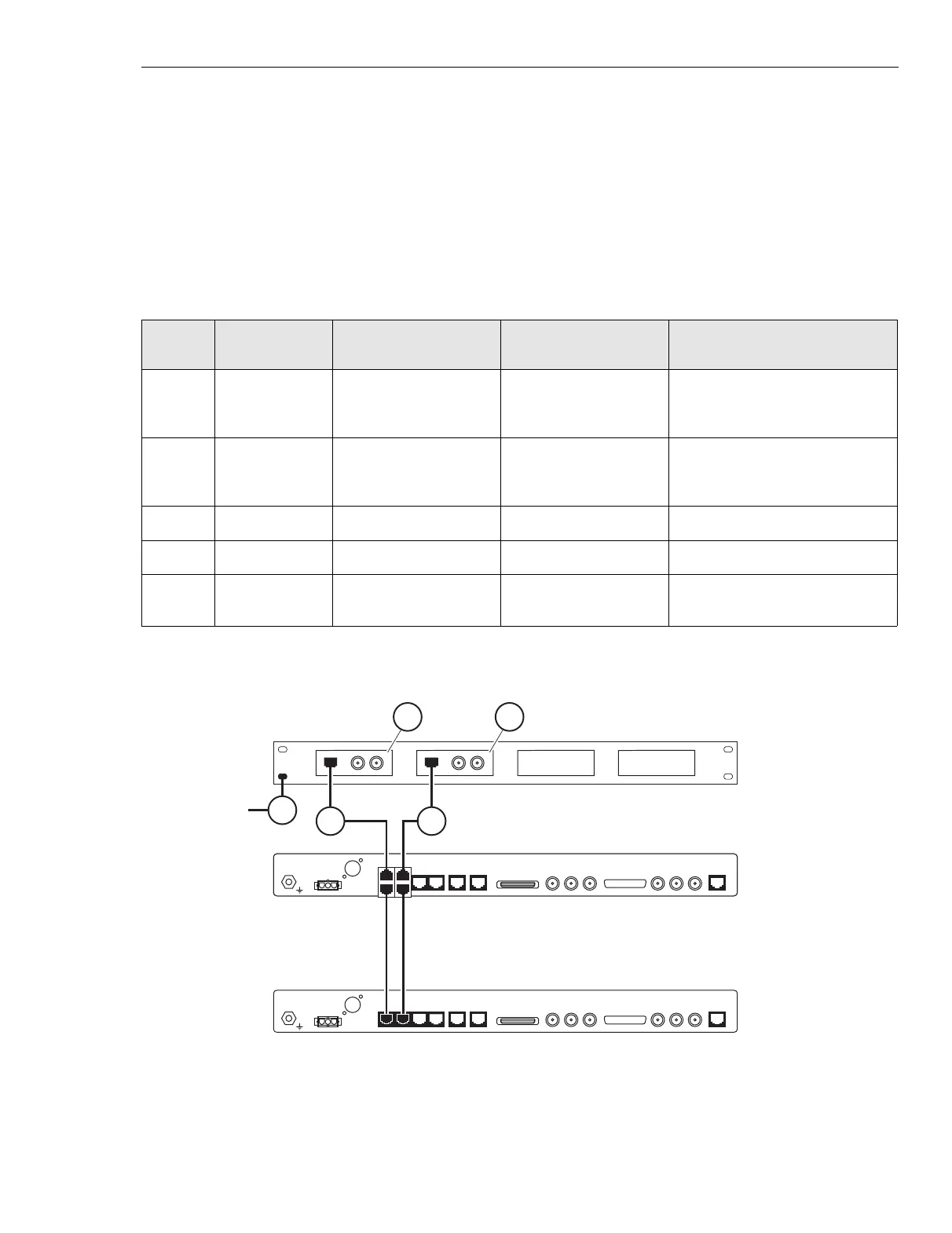
Table C-2 identifies and Figure C-3 shows site controller E1 75Ω (2.048
Mb) cabling.
Note: All cabling for E1 75Ω Control Racks is the same as that shown in
Table C-1. In addition, the following cables shown in Table C-2 are
necessary for E1 75Ω communication.
Table C-2 Site Controller E1 75
Ω
(2.048 Mb) cabling
Index
number
Part
number
From To Notes
38 3084225N48
Modular T-Adapter on
Controller A, T1/E1-1
Connector
E1-1 75Ω Balun
transformer
39 3084225N48 Modular T-Adapter on
Controller A, T1/E1-2
Connector
E1-2 75Ω Balun
transformer
40 0182694Y01 - - 75Ω Balun transformer
41 0182694Y01 - - 75Ω Balun transformer
42 3082000X12 Mounting screw on
Balun panel
Rack Ground system
iSC400
102600JNM
10B2-1123 10/100B-T10B2-210B2-3
X.21
SITE REF OUT
PARALLELSERIALREDUND4321
T1/E1
GPS
-48V RTN
BAT
iSC400
102600JNM
10B2-1123 10/100B-T10B2-210B2-3
X.21
SITE REF OUT
PARALLELSERIALREDUND4321
T1/E1
GPS
-48V RTN
BAT
iSC400
102600JNM
10B2-1123 10/100B-T10B2-210B2-3
X.21
SITE REF OUT
PARALLELSERIALREDUND4321
T1/E1
GPS
-48V RTN
BAT
iSC502
032801JNM
TO RACK
GROUND
SYSTEM
38 39
4041
42
Figure C-3 75
Ω
E1 (2.048 Mb) Cabling
 Loading...


