Appendix B Parts & Suppliers Gen 3 Site Controller System Manual
B-10 68P80801E30-A 5/1/2002
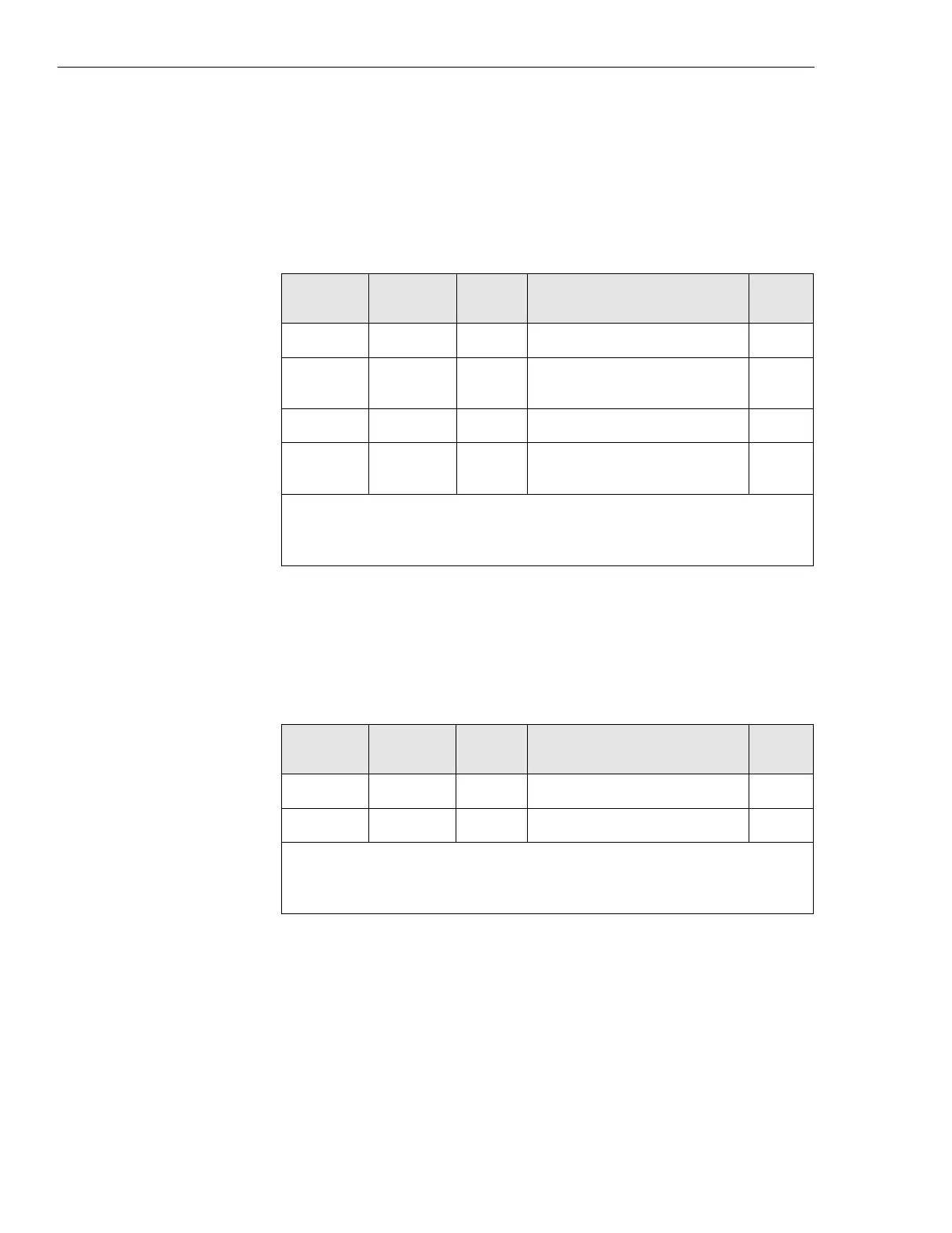
Selecting master ground bar lugs
Table B-1 identifies recommended part numbers for wire lugs used to
connect chassis ground wiring to the master ground bar from each cabinet.
Selecting cabinet ground lugs
Table B-2 identifies recommended part numbers for wire lugs used to
connect chassis ground wiring to the grounding point of each cabinet.
Battery system connections
The cable loop length refers to the total length of wire within a given circuit.
For example, the combined length of the -48 Vdc (hot) lead and the DC
return lead equals the cable loop length. This means that a cabinet that needs
16 feet of wire between the batteries and Power Supply Rack has a total loop
length of 32 feet.
Table B-1 Recommended master ground bar lugs
Wire size Wire type
Lug
color
Description P/N †
#2 AWG stranded brown single 1/4” diameter hole 54107
#2 AWG stranded brown double 1/4” diameter hole, 5/8”
center
54207
#6 AWG stranded blue single 1/4” diameter hole 54105
#6 AWG stranded blue double 1/4” diameter hole, 5/8”
center
54205
NOTE:
These lugs require the use of the TBM5-S crimping tool.
† All part numbers are Thomas & Betts.
Table B-2 Recommended Junction Panel ground lugs
Wire size Wire type
Lug
color
Description P/N †
#2 AWG stranded brown single 1/2” diameter hole 54145
#6 AWG stranded blue single 3/8” diameter hole E6-12
NOTE:
These lugs require the use of the TBM5-S crimping tool.
† All part numbers are Thomas & Betts.
 Loading...


