Home
Panduit
Power distribution unit
smartzone G5
Panduit smartzone G5 User Manual
5
of 1
of 1 rating
152 pages
Give review
Manual
Specs
To Next Page
To Next Page
To Previous Page
To Previous Page
Loading...
INTE
LLIG
ENT P
DU USE
R MAN
UAL
105
Warranty
and Regulatory Information
Warranty Inform
a
tion
(
http
://www.P
an
duit.c
om
)
Regulatory Inform
ation
Safety an
d reg
ul
atory co
mpl
ian
ce
For im
portant
safet
y,
enviro
nmenta
l,
and regul
atory i
nf
ormat
ion,
see
Saf
ety and
Compl
ianc
e Infor
matio
n
at
the
Pand
uit
websit
e
(
http://w
ww.Pa
ndui
t.com
)
104
106
Table of Contents
Table of Contents
2
Section 1 - System Overview
9
PDU Controller
9
Connecting the PDU Via Ethernet Port
9
Figure 1: Ethernet Port for Network Connection
9
Connecting the PDU to a Computer Serial Port
10
Figure 2: Status LED & Serial in Port Identified
10
Section 2 - Web Graphical User Interface (GUI) Configuration
11
Internet Protocol (IP) Addressing
11
Connecting to the PDU
11
Web Configuration
11
Figure 3: Changing Your Password
12
Figure 4: after Login
12
Figure 5: Change User Password
13
Figure 6: Change Password
13
Introduction to the Web GUI
15
Figure 7: Login Page
15
Figure 8: Landing Page/Dashboard
15
Screen Resize Due to Multiple PDU Configuration
17
Figure 9 - Resized Dashboard Screen
17
Menu Dropdowns
18
Introduction to the Dashboard
18
Figure 10: Power Summary Page
18
Network Settings
19
Figure 11: Outlet Monitoring Page
19
Figure 12: Environmental Monitoring Page
19
Figure 13: Security Monitoring Page
19
System Management Information
21
Figure 14: System Management
21
Figure 15: System Management Configuration
22
Figure 16: Rack Location Configuration
23
Setting Time and Date on the PDU
24
Figure 17: Power Panel & Core Location
24
Figure 18: NTP Configuration
25
Figure 19: Daylight Saving Time Configuration
26
Outlet Power Management
27
Outlet Power Sequence Setup
28
Figure 20: Control & Manage PDU
28
Figure 21: Outlet Control Enabled
29
Figure 22: Edit Outlets
29
Setting Metering Thresholds
30
Figure 23: One-Delay Time
30
Figure 24: Saved Sequence
30
Figure 25: Power Threshold
31
Figure 26: Energy Threshold
33
Figure 27: Phase Current Alarm
34
Figure 28: Phase Voltage Alarm
36
Figure 29: Load Segment Breaker
38
Figure 30: Device Detection Threshold Information
40
Figure 31: Outlet Information
41
Email Setup
42
Figure 32: Email Setup
43
Figure 33: SMTP Account Settings
44
Figure 34: Email Recipients
45
Data Log
46
Figure 35: Data Log
46
Web Interface Access
47
Figure 36: Data Log Configuration
47
Setting up the System for RADIUS Authentication
49
Figure 37: User Settings
49
Configuring the System with LDAP Server Settings
50
Figure 38: RADIUS Configuration
50
Figure 39: LDAP Configuration
52
Figure 40: Enable Role Privileges
53
Figure 41: Test LDAP Configuration
54
Section 3 - Simple Network Management Protocol (SNMP)
55
SNMP Management Configuration
55
Figure 42: SNMP Management
55
Figure 43: SNMP General
56
Configuring Users for SNMP V1/V2C
57
Figure 44: SNMP Port
57
Figure 45: Setup SNMP Port and Trap Port
57
Figure 46: Define SNMP V1/V2C User
58
Figure 47: Edit V1/2C Manager
58
Configuring Users for SNMP V3
59
Figure 48: SNMP V3 Manager
59
Figure 49: SNMP V3 Edit
60
Configuring SNMP Traps
61
Figure 50: Snmpv2 Configuration Information
61
Figure 51: Snmpv3 Trap Server Information
62
Section 4 - Local Display
64
Onboard Display and Network Controller
64
Figure 52: Network Controller
64
Control Buttons
65
Network Controller Menu Structure
66
Main Menu Selections
66
Figure 53: Network Controller Menu Structure
66
Setup Menu
67
Figure 54: Main Menu Selections
67
Figure 55: Setup Menu
67
Figure 56: Network Submenu
68
Figure 57: Device Submenu
69
Figure 58: Screen Submenu
70
Figure 59: Language Submenu
71
Figure 60: USB Submenu
72
Figure 61: Units Submenu
73
Figure 62: Alarms Menu
74
Figure 63: Power Menu
75
Figure 64: Device Submenu
76
Figure 65: Phase Submenu
77
Figure 66: Breaker Submenu
78
Figure 67: Outlet Submenu
79
Sensors Menu
80
Figure 68: Sensors
80
Section 5 - Daisy Chain Configuration
81
Daisy-Chain Overview
81
Daisy-Chain Setup
81
RNA (Redundant Network Access) Functionality
81
RNA Setup
82
Figure 69: Connection Diagram RNA Daisy Chain
82
Power Share
84
Figure 70: Connection Diagram Power Share & Daisy Chain
85
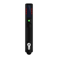
Section 6 - Smartzone Security Handle
87
Figure 71: Smartzone Security Handles
87
Figure 72: Connection Diagram for Smartzone Security Handle
88
Configuring Cabinet Access Control
89
Figure 73: Rack Access Control Web GUI
90
Figure 74: Rack Access Control Actions Web GUI
90
Adding a User for Local Rack Access
91
Configuring Rack Access Settings
92
Figure 75: Local Rack Access Web GUI
92
Configuring Handle Settings
93
Figure 76: Rack Access Settings Web GUI
93
Configuring Keypad Settings
94
Figure 77: Handle Settings Web GUI
94
Remote Controlling the Handle
95
Figure 78: Remote Control
96
Controlling the Beacon
97
Figure 79: Beacon
97
Figure 80: Beacon Settings Web GUI
98
The Status LED
99
Setting Status LED State
100
Handle and Compatible Card Types
100
Figure 81: Status LED Settings Web GUI
100
Section 7 - Smartzone G5 Accessories
101
Hardware Overview
101
Figure 82: Sensor Ports for Vertical PDU
102
Configuring Temperature Scale
103
Configuring Environmental Sensors
103
Figure 83: Sensor Ports for Horizontal PDU
103
Figure 84: User Settings
103
Figure 85:Celcius Setting
103
Figure 86: Fahrenheit Setting
103
Warranty and Regulatory Information
105
Warranty Information
105
Regulatory Information
105
Panduit Support and Other Resources
106
Accessing Panduit Support
106
Acronyms and Abbreviations
107
Appendix A: Sensor Configuration
108
Door Switch Sensor
108
Dry Contact Input Sensor (Side Panel Switch)
108
Temperature & Humidity Sensors
109
Figure 88: Door Switch Sensor Configuration
109
Configuring Environmental Sensors
110
Figure 89: Dry Contact Cable
110
Figure 90: Temperature and Humidity Sensors
111
Appendix B: Firmware Upgrade Options
112
Web Interface Method
112
G5 Upgrade Utility (GUT)
112
Figure 91: Sensor Ports on Controller
112
USB Method
113
Ftps Method
113
Figure 92: Upload Firmware
113
Appendix C: Bulk Management of Pdus
115
G5 Upgrade Tool (GUT)
115
Figure 93: G5 Upgrade Tool Interface
116
Figure 94: System Management Screen Webgui
117
Figure 95: G5 Upgrade Tool Interface
117
Appendix D: System Reset or Password Recovery
118
Figure 96: Example CSV File
118
Figure 97: G5 Upgrade Tool Interface
118
Appendix E: PDU Alarms
119
Trap Codes Assigned to Alarms List
121
Appendix F: Panduit Network Controller Replace or Rotate 180
127
Figure 98: Screws on Network Controller
128
Appendix G: Direct Connect to the PDU by Changing Your Pc's IP Address
129
Figure 99: Ribbon Cable for the Network Controller
129
Figure 100: Control Panel
130
Figure 101: Network Status and Tasks
131
Figure 102: Change Adapter Settings
132
Figure 103: Properties
132
Figure 104: Ethernet Properties
133
Figure 105: Internet Protocol Version 4
134
Appendix H: Command Line Interface (CLI)
135
Figure 106: IP Settings for Direct Connection
135
Figure 107: Connect MA017 to the PDU In/Serial Port
137
CLI Commands
138
Figure 108: Serial Cable Pinout
138
Network Commands
140
User Commands
142
Device Commands
142
Appendix I: RADIUS Server Configuration
147
Appendix J: Panduit G5 Accessories
149
Appendix K: Compliance Model Number Details
150
Appendix L: JSON API Web Service
151
Other manuals for Panduit smartzone G5
Installation Guide
20 pages
Manual
2 pages
5
Based on 1 rating
Ask a question
Give review
Questions and Answers:
Need help?
Do you have a question about the Panduit smartzone G5 and is the answer not in the manual?
Ask a question
Panduit smartzone G5 Specifications
General
Brand
Panduit
Model
smartzone G5
Category
Power distribution unit
Language
English
 Loading...
