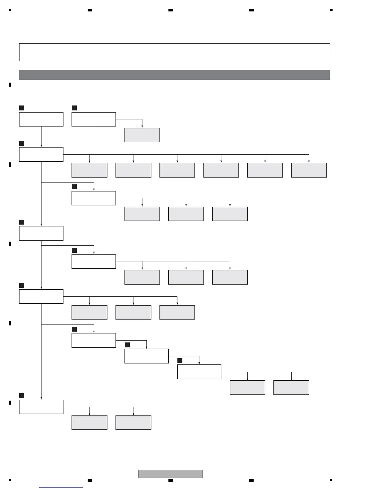
7. DISASSEMBLY
It is efficient to proceed with removal of the main parts and boards in the order shown in the chart below:
Note: Even if the unit shown in the photos and illustrations in this manual may differ from your product, the procedures
described here are common.
Flowchart of removal order for the main parts and boards
1
Side input cover
1
Rear case (509)
3
Under cover (509)
2
Side input shield
1
Power button case
SIDE IO
SENSOR
SIDE KEY SIDE HDMI
50F Y DRIVE 50F X DRIVE PC
POWER SW
4
T panel U Assy
MAIN IO_AUDIO 50F DIGITAL
6
7
7
Front bezel
(509TVU)
8
F. Chassis VL
Assy 50
Sub frame L Assy (50)
Sub frame R Assy (50)
F. Chassis HT Assy 50
F. Chassis HB 50
LED RLS
50F SCAN A 50F SCAN B
IR
POWER
SUPPLY
50F
ADDRESS L
50F
ADDRESS S
FAN
CONNECT
7
Address heatsink
S, L
 Loading...