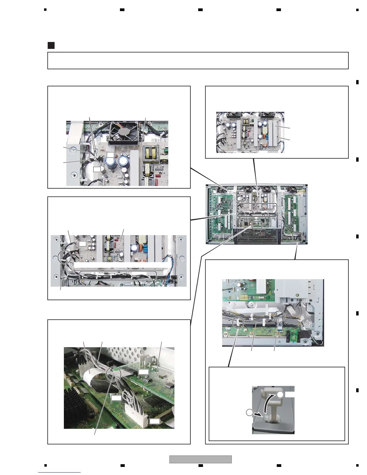
Notes on Lead Dressing
Note: The wiring shown in the photo is different from the actual wiring, because the product in the photo is a prototype.
Upon servicing, be sure to restore the original wiring of the unit after repair work.
How to remove the newly adopted wire saddle
from the chassis
POWER SUPPLY Unit
P1
P2
P5
PC1
IO5
IO6
Tape (white)
J102
POWER SUPPLY Unit
PC AssyJ215 J118
J101
J111 (black and white)
The J101 and J102 cables require correct orientation for
connection. Connect the connectors with white tape to the
POWER SUPPLY Unit.
Dress so that J111 passes over other cables.
Pass J215 over J118.
Push
Pull out
1
2
POWER SUPPLY Unit
PCB base
When removing the POWER SUPPLY Unit, be sure to
remove not only the POWER SUPPLY Unit but entire PCB
base.
Around the periphery of the Multibase, the J111 cable
wires (black and white) must be bound lastly then be
dressed so that they pass over other cables.
The J215 cable must be passed over the J118 cable.
Dress the J118 cable so that it passes over other cables.
J118
Dress the J118 so that it passes
over other cables.
Dress the J111 so that it passes under other cables.
 Loading...