DELAY ADJUSTMENT OF THE CONTROL SIGNAL (SUS-D)
1 Measure the pulse width of the SUS-D signal.
2 Check the pulse width of the SUS-D input signal (gate terminal of Q2111).
Adjust the variable control so that the pulse width of the SUS-D input signal (gate terminal of Q2111) becomes the
same pulse width ± 5 nsec as the SUS-D signal.
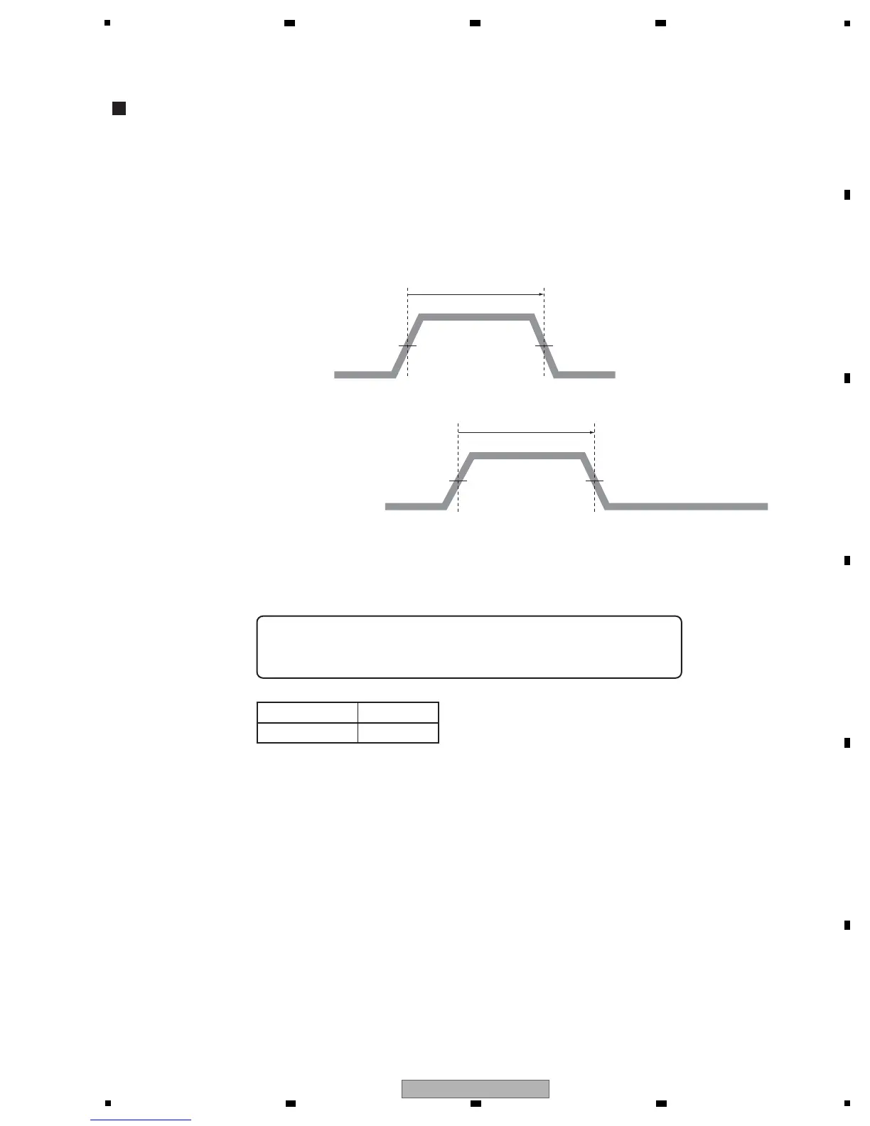
Note: • For details on measuring points of waveform, see the figure below.
50 % of the crest value 50 % of the crest value
50 % of the crest value 50 % of the crest value
SUS-D pulse width: Tsus - Dg
Adjust so that "Tsus - Dg = Tsus - D ± 5 nsec," using the variable
control shown in the table below:
SUS-D signal
(input to the DRIVE Assy)
SUS-D signal
(input to the gate terminal of Q2111)
SUS-D pulse width
Tsus - D
SUS-D pulse width
Tsus - Dg
Assy VR
Y DRIVE Assy VR2001
 Loading...