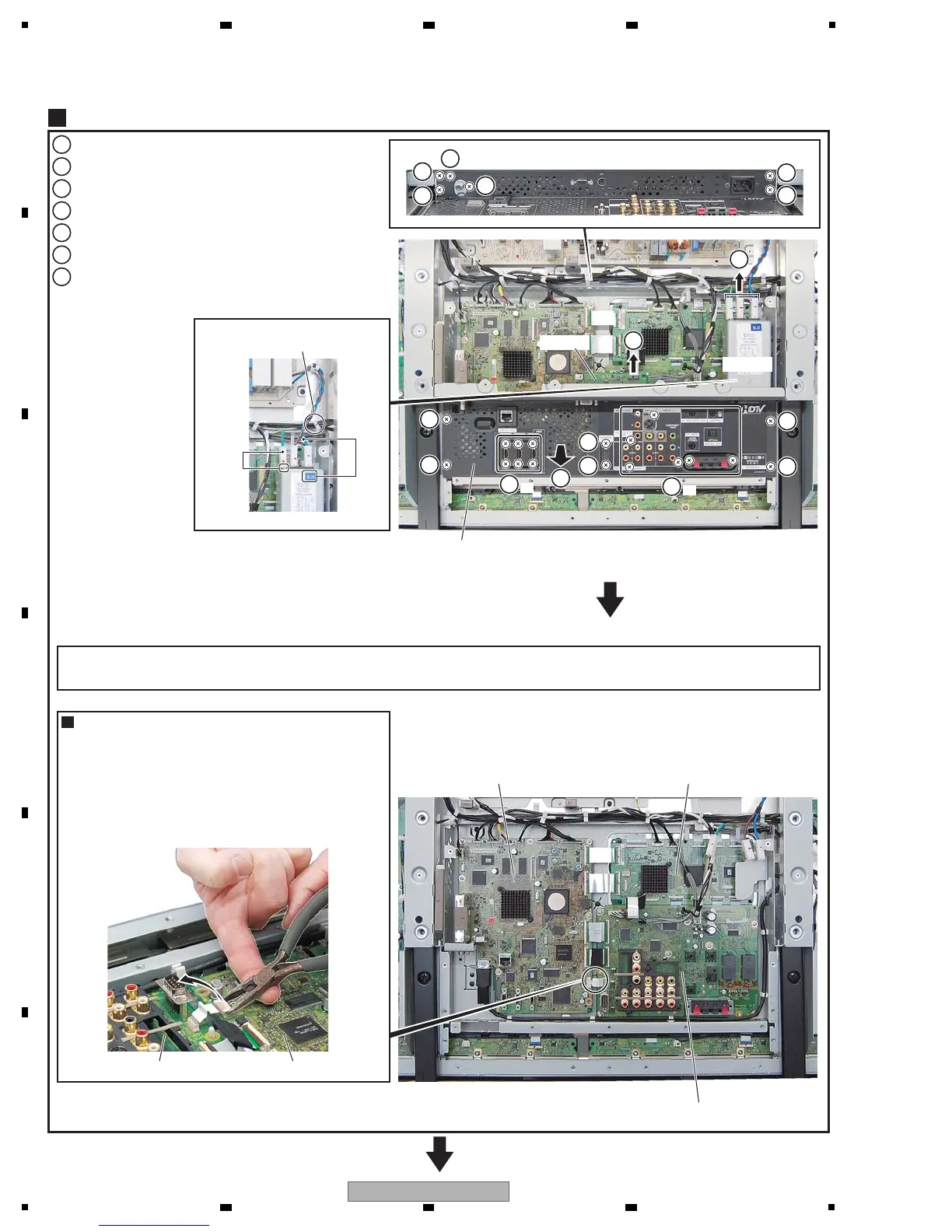
Remove the 10 screws. (ABA1377)
1
Remove the six screws. (BPZ30P080FTB)
2
Remove the two hexagon head screws. (ABA1382)
3
Remove the six screws. (BMZ30P060FTB)
4
Disconnect the one flexible cable.
5
Disconnect the three connectors.
6
Remove the T panel U Assy.
Do NOT pass the AC inlet jumper
wire through this wire saddle.
7
T Panel U Assy
4
T panel U Assy
PC Assy
AC inlet
MAIN AssyIO_AUDIO Assy
IO_AUDIO Assy
50F DIGITAL Assy
MAIN Assy
1
1
1
1
1
1
1
1
1
1
2
3
3
5
6
7
×6
4
×6
(1) Grip the two short edges of the connector with longnose
pliers.
(2) Insert a finger between the longnose pliers and the board
to protect the board and the mounted parts on the board
from accidental damage by the pliers then, using your
finger as a fulcrum and the pliers as a lever, pry the
connector upward to remove it.
How to remove the bridge connector
Note: The wiring shown in the photo is different from the actual wiring, because the product in the photo is a prototype.
Upon servicing, be sure to restore the original wiring of the unit after repair work.
Blue
GND
AC inlet
 Loading...