7.14
CLUTCHING
removed.
2. Install the head of the weight pin (12) so that it is on the leading side of rotation. This will orientate the nut (11) on the trailing
side of rotation.
3. Torque weight pin to 30 in-lb (3Nm).
4. Place the moveable sheave (8) onto the stationary sheave (10).
5. Place the same number of spacers (18) under the stepped washer (17) onto the shaft of the stationary sheave.
6. Thread the spider onto the stationary sheave shaft.
7. Index the spider. See “SPIDER INDEXING” on page 7.15
8. Using the spider tool (PN 2870341) torque to 200 ft-lb (276Nm).
9. Install the jam nut (6) onto the shaft and torque it to 235 ft-lb (324 Nm).
10. Place the drive spring on the shaft.
11. Place the cover (3) onto the clutch and torque the cover fasteners (2) to 90 in-lb (10Nm).
NOTE: DO not allow side loading or mis-alignment of the cover or the bushing may become damaged.
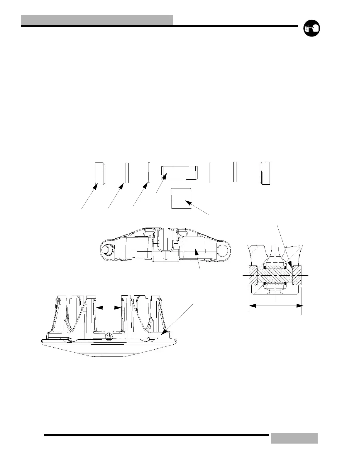
DRIVE CLUTCH SPIDER REMOVAL/INSTALLATION
ROLLER REMOVAL
1. With the spider in a vise start removing the spider buttons (1) by drilling a 0.18" hole in the center of a button on one side of
the spider.
2. Place spider (6) on a vise or in an arbor press.
3. Place a pin punch through the spider button hole and drive the opposite button and pin (4) out.
4. Remove shims (2) (if any are installed) and note their location.
5. Flip the spider over and tap out the holed button.
A
E
C
B
F
G
H
L
K
D
 Loading...