8.8
FINAL DRIVE
8.37 CHAINCASE REMOVAL
1. Support the rear of the machine and loosen up the track
tension.
2. Remove RH side panel.
3. Remove the exhaust system, see “EXHAUST
REMOVAL” on page 3.16.
4. Remove the plenum.
5. Remove drain plug and drain the chaincase fluid.
6. Once fluid is drained replace drain plug and torque to 8 ft-
lb (11Nm).
7. Remove the speedo drive on the drive shaft to gain access
to the drive shaft retaining nuts.
8. Remove driveshaft retaining nuts.
9. Remove the torx screw that holds on the cowling on the
LH side.
10. Remove the torx screws that hold the oil/coolant bottles to
the bracket. This will give you room to remove the caliper
later.
11. Move the LH cowling away from the footrest and remove
the LH storage compartment by prying the top and sides of
the compartment in to clear the foot rest. This will give
you room to access the chaincase retaining bolts.
12. Apply the parking brake.
13. Tip machine over on its LH side.
14. Remove the chaincase cover and clean it.
15. Remove the lower sprocket bolt and washer (X,Y).
16. Remove the cotter pin (D) on the jackshaft.
17. Remove the jam nut (E) and washer (F) on the jackshaft
(upper sprocket).
18. Release the parking brake.
19. Release the tension on the chaincase tensioner (H).
20. Remove the sprockets (G,W) and chain (V) from the
chaincase.
21. Remove the brake caliper bolts.
22. Push the coolant hose enough to remove the caliper out of
the way of the chaincase.
23. Remove the rear suspension.
24. Carefully slide the driveshaft down so that it clears the
chaincase, and remove the driveshaft.
25. Remove the track from the chassis.
26. Remove the chaincase retaining bolts.
27. Slide the chaincase out of the chassis.
28. Inspect the o-ring and seal sleeve on the jackshaft and
replace the o-ring.
29. Service the chaincase outlined in “CHAINCASE SEAL/
BEARING REPLACEMENT” on page 10.
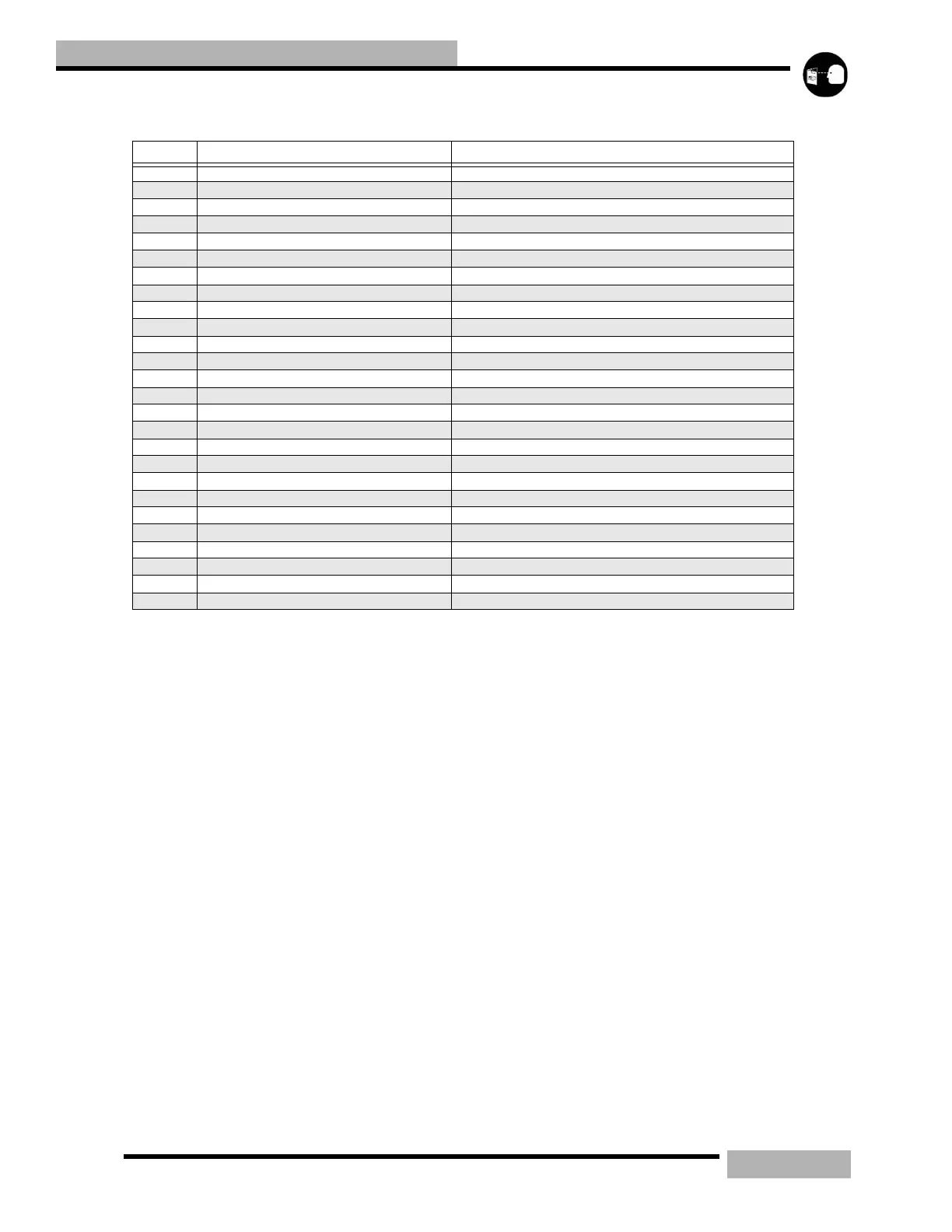
Table 8-7: Chaincase
ITEM DESCRIPTION TORQUE SPECIFICATION / NOTES
A Cover bolts 8 ft-lb(11Nm)
B Chaincase cover
C Cover gasket make sure that the gasket is not pinched during assembly
D Cotter pin bend the ends over the nut flats when installing
E Jackshaft nut 50 ft-lb (62.5Nm)
F Washer
G Top sprocket Install so that the shoulder is facing the bearing
H Chain tensioner adjuster Torque only finger tight during assembly
I Tensioner lock nut
J Fastener Seal Thread this onto the adjuster bolt during assembly
K Tensioner Assembly
L Upper c-clip Install so that the chamfered edge is facing the bearing
M Upper bearing Loctite 680 when assembled
N Breather roll pin
O Chaincase
P Upper seal Install so that the lip is facing the chaincase
Q Lower seal Install so that the lip is facing the chaincase
R Fill plug
S Drain plug 8 ft-lb (11Nm)
T Lower bearing Loctite 680 when assembled
U Lower c-clip Install so that the chamfered edge is facing the bearing
V Chain
W Lower sprocket Install so that the shoulder is facing the bearing
X Washer
Y Lower sprocket retaining bolt 19 ft-lb (26Nm)
Z Sight glass Only remove if replacing
 Loading...