7.16
CLUTCHING
PN 5210752.020" (.5mm)
4. Install spider washer(s) and spider aligning the “X” with
the moveable sheave’s “X”. Notice as the spider seat
location is changed, the sheave marks made before
disassembly no longer align (C). There are two ways to
bring the sheave marks into alignment.
Vary the amount and thickness of spacer washers (washer
thickness may vary slightly). Re-index marked spider leg to
another tower. This can be done because spider has little effect
on overall clutch balance.
Re-indexing the spider 1/3 turn clockwise, or 1 leg, will allow
the realignment of the moveable and stationary sheaves as
previously marked (D). For EXAMPLE: 0.020" or 0.032" (0.5
- 0.8mm) washer removed - re-index spider clockwise 1/3
turn.
NOTE: Alignment marks on the sheaves should be
with in 1" (.25mm) after final assembly and torquing.
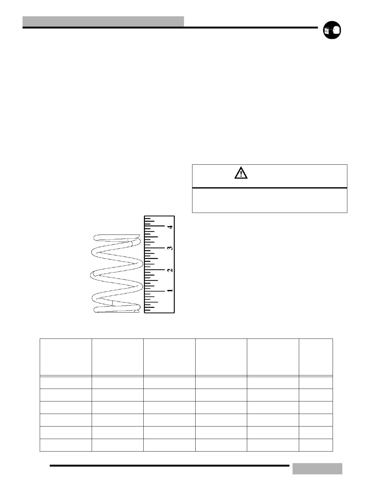
SPRING
FREE
LENGTH
Maximum
efficiency of the
variable speed
drive system is
dependent upon
many factors.
Included in these
are clutch offset
and alignment,
belt tension, belt to sheave clearance, and internal condition of
the drive and driven clutch components. One of the most
critical and easily serviced parts is the drive clutch spring. Due
to the severe stress the spring is subject to during operation, it
should always be inspected and checked for tolerance limits
during any clutch operation diagnosis or repair.
With the spring resting on a flat surface, measure free length
from outer coil surfaces as shown. Refer to the chart above for
specific free length measurements and tolerances.
In addition to proper free length, the spring coils should be
parallel to one another when placed on a flat surface.
Distortion of the spring indicates stress fatigue. Replacement
is required.
New springs that are introduced will be black in color with the
last four digits of the spring part number, and the load rating in
white ink on the outer diameter of the spring located and the
mid height of the spring.
EXAMPLE: Spring PN 7042287 has a load rating of 110/290.
The designation printed on the spring would be “2287 110/
290”.
CAUTION
Never shim a drive clutch spring to increase its compression
rate. This may result in complete stacking of the coils and
subsequent clutch cover failure
Table 7-4: Drive Clutch Springs
PART
NUMBER
COLOR
WIRE
DIAMETER
(inches)
FREE LENGTH
+/-.125”
FORCE
LBS.@2.50” -
1.19” (+/- 12
LBS.)
LOAD
RATE
(lbs./
inch)
7041021 No paint color .157” 4.14 70-130 44
7041022 Black .140” 4.25” 44-77 25
7041063 Purple .168 4.37 75-135 53
7041062 Silver .207 3.12 75-243 151
7041065 Pink .177 4.69 112-200 64
7041060 Orange .196 3.37 70-199 98
 Loading...