Chapter 2: Basic Operations
DXi4700 Node
Quantum DXi4700 User’s Guide 36
l DXi4700 Node Front Panel Features and Indicators below
l DXi4700 Node Rear Panel Features on page 39
l DXi4700 Node 1 GbE Ethernet on page 42
l DXi4700 Node 10 GbE Ethernet Port Indicators on page 43
l DXi4700 Node 10 GBase-T Ethernet Port Indicators on page 44
l DXi4700 Node Power Supply Indicators on page 44
DXi4700 Node Front Panel Features and Indicators
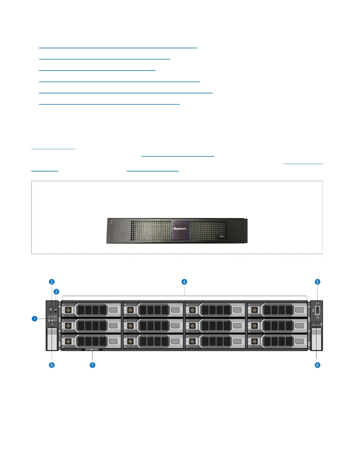
Figure 15 below shows the controls, indicators, and connectors located behind the optional rack bezel on
the front panel of the DXi4700 G1 Node. Figure 16 on the next page shows the controls, indicators, and
connectors located behind the optional rack bezel on the front panel of the DXi4700 G2 Node.Table 1 on the
next page describes each item and Table 2 on page 38 describes each diagnostic indicator.
New DXi Bezel
A new DXi bezel is available. Please contact your account sales manager to purchase additional new
bezels.
Figure 15: DXi4700 G1 Node - Front View
 Loading...