Chapter 2: Basic Operations
DXi4700 Expansion Module
Quantum DXi4700 User’s Guide 49
DXi4700 Expansion Module EMM Features and
Indicators
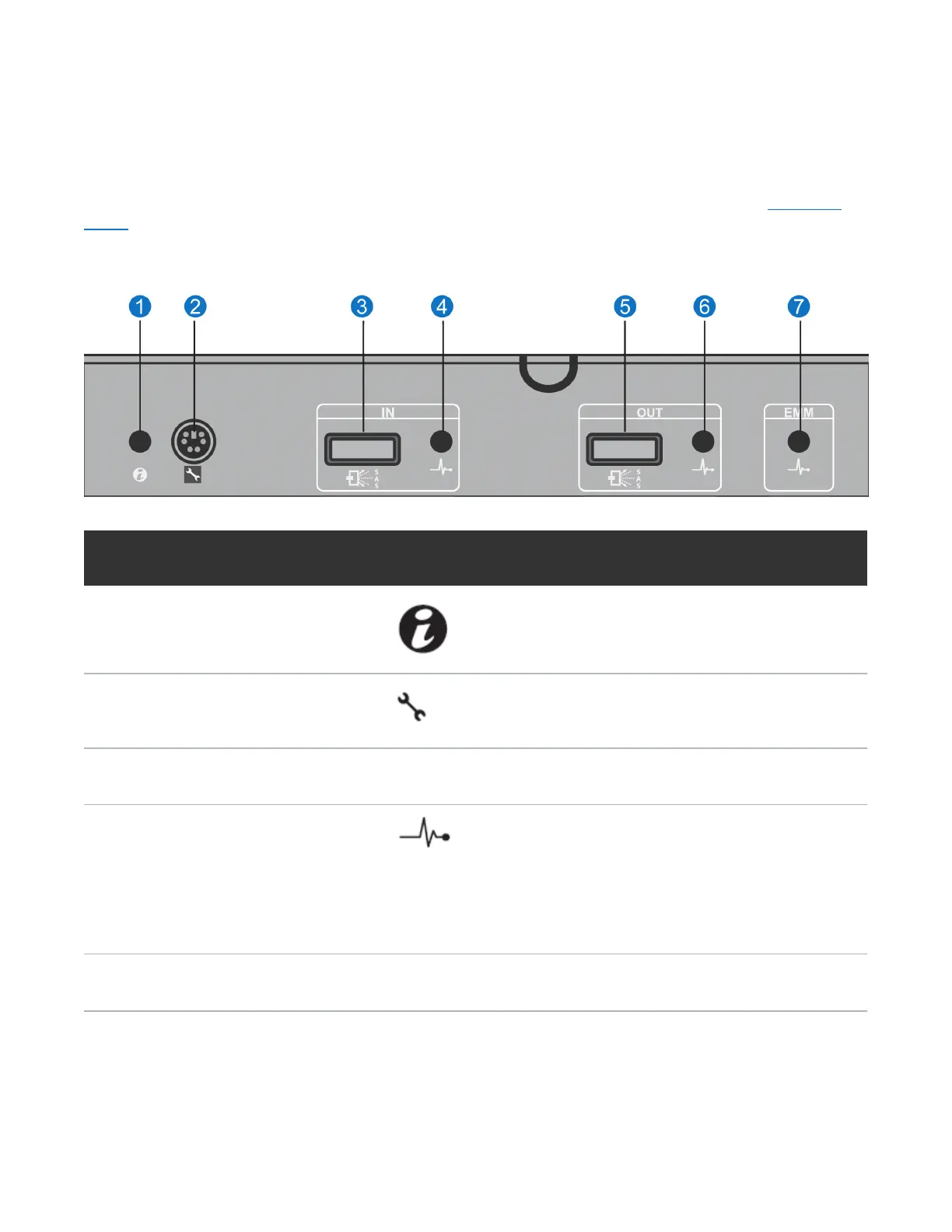
Each DXi4700 G1 Expansion module contains two enclosure management modules (EMMs). Figure 26
below shows the connectors located on the rear panel of the EMM.
Figure 26: DXi4700 G1 Expansion Module EMM - Rear View
Item Indicator, Button, or
Connector
Icon Description
1
System status indicator Blinks blue when the system identification button is
pushed. You can identify a particular enclosure in a
rack using the system identification indicator.
2
Debug port Not used.
3
SAS port (In) Provides connection from the Node or another
Expansion module.
4
SAS port (In) link status Indicates SAS port status:
Lights green when all the links to the port are
connected.
Lights amber when one or more links to the port are not
connected.
The LED remains off if enclosure is not connected.
5
SAS port (Out) Provides connection from the Expansion module to
another Expansion module.
 Loading...