381/617
Building Technologies Division User Manual LMS14… CC1U7471en
6 The settings in detail 28.01.2015
6.23.1 Manual setting/adaption of partial diagrams
A plant diagram is composed of several partial diagrams. The desired plant diagram
can be manually created by using the required partial diagrams.
But it is also possible to adapt partial diagrams that were generated via Presetting
(5700).
The catalog with the partial diagrams, which is available as a separate document,
contains all partial diagrams implemented in the controller – assigned in the form of
groups. In addition, the line no. required for creating the respective partial diagrams and
the associated sensors are listed.
Note!
Check no. heat source 1 (6212), Check no. heat source 2 (6213), Check no. storage
tank (6215), and Check no. heating circuits (6217) can be used to check whether the
settings led to the correct partial diagram. The check no. shown there must accord
with the partial diagram no. of the respective component group.
6.23.2 Heating circuits/cooling circuit
Line no. Operating line
HC1 HC2 HC3
5710 5715 5721 Heating circuit 1, 2, 3
Off
On
Using this setting, the heating circuits can be switched on and off.
Off
Function is deactivated.
On
Function is activated.
Line no. Operating line
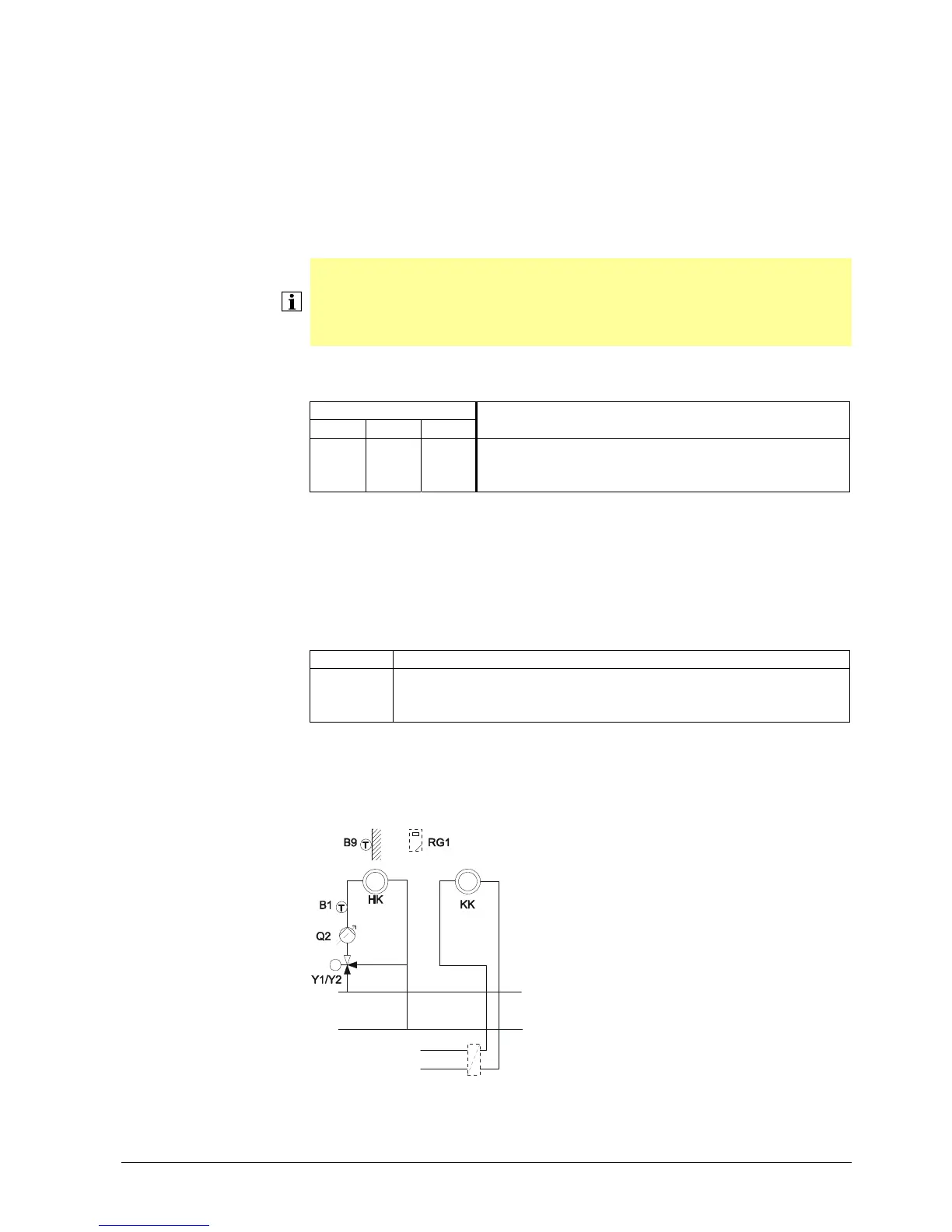
5711 Cooling circuit 1
Off
4-pipe system cooling
Off
The cooling circuit is switched off.
4-pipe system cooling
7471z117/1209
Cooling and heating circuit draw their
cooling/heating energy from separate
primary circuits.
Heating circuit 1, 2, 3
Cooling circuit 1

 Loading...