589/617
Building Technologies Division User Manual LMS14… CC1U7471en
8 Technical data 28.01.2015
8.1.4 Electrical connection data, extra-low voltage connections
(PELV)
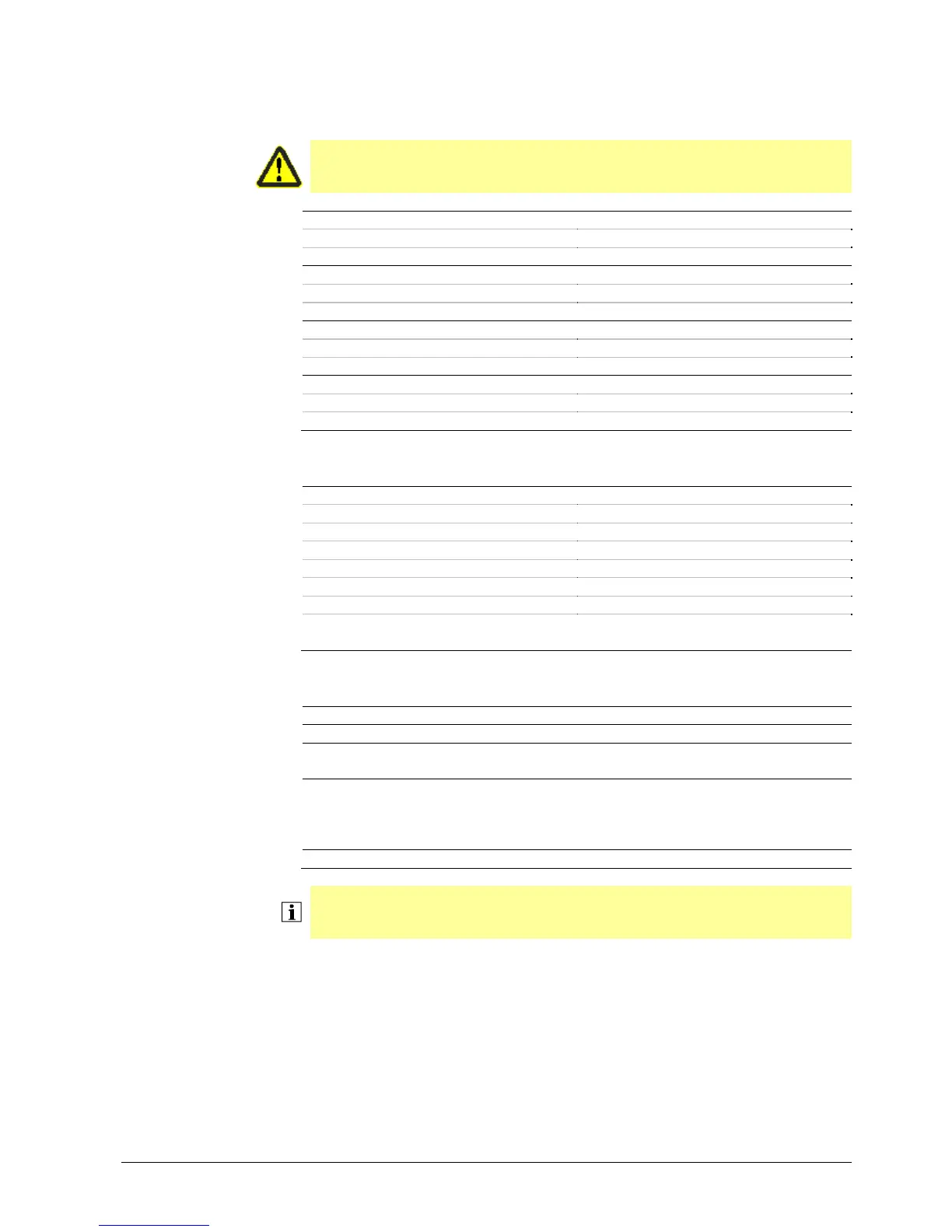
8.1.4.1. Supply voltage outputs, general data
Warning!
For functional reasons, the LMS14 extra-low voltage circuits are connected to
the protective earth via X17. Therefore, they are classed as PELV circuits.
+5 V
- Output voltage LMS14 DC 5 V ±5%
- Short-circuit current (current limitation) Imax. 1 A
+12 V
- Output voltage LMS14 DC 12 V ±5%
- Short-circuit current (current limitation) Imax. 0,8 A
+15 V
- Output voltage LMS14 DC 15 V ±5%
- Short-circuit current (current limitation) Imax. 1,5 A
+24 V
- Output voltage LMS14 DC 24 V ±5%
- Short-circuit current (current limitation) Imax. 1,1 A
8.1.4.2. Input B2
Sensor B2 NTC 10 k
- Continuous temperature Max. 100 °C
- Short-time temperature Max. 125 °C
- Sensor tolerance ±2 K
- Cable length 3 m
- Aging ±3%
- 20 s
- Other requirements Conformity to DIN EN 60730-2-9 and DIN
EN 14459:2007 Annex K
8.1.4.3. Inputs B7/BX4
Sensor (B7)/multifunctional sensor BX4 (X4)
- Resistance value
- Sensor (B7) NTC 10k
Refer to boiler sensor (B2)
- Multifunctional sensor (BX4) NTC 10k (QAZ36…, QAD36…)
NTC 20k (flue gas sensor)
Pt1000 optional for collector sensor and
flue gas sensor)
- Cable length 3 m
Note!
Sensor input BX4 is firmly assigned to sensor B7. Reading in of sensor B7 is safety-
related.

 Loading...