Connecting the bus connector
Proceed as follows to connect the bus connector:
1.
Plug the bus connector into the corresponding interface of the control unit.
2. Screw the bus connector into place.
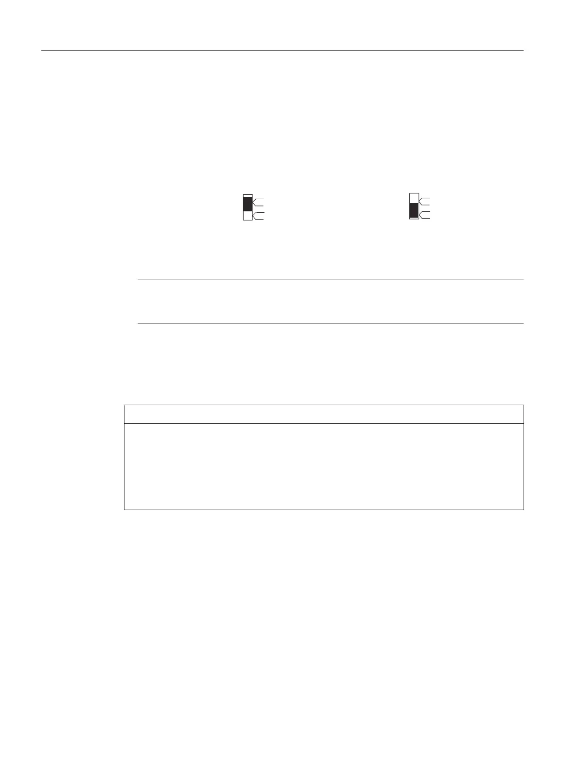
If the control unit is located at the start or end of a segment, you must switch on the
terminating resistor ("ON" switch setting).
7HUPLQDWLQJUHVLVWRU
VZLWFKHGLQ
7HUPLQDWLQJUHVLVWRU
QRWVZLWFKHGLQ
RII
RQ
RQ
RII
Figure 4-7 Terminating resistor "switched on" or "switched off"
Note
Make sure that the nodes at which the terminating resistor is located are always supplied
with voltage during startup and operation.
Removing the bus connector
You
can remove the bus connector with a looped-through bus cable from the PROFIBUS DP
interface at any time without interrupting data traffic on the bus.
NOTICE
Data communication disturbed because bus terminator missing
A bus segment must be terminated at both ends with a terminating resistor. This is not the
case
if the last bus connector node is de-energized, for example. Because the bus connector
takes its voltage from the station, this terminating resistor is ineffective.
Make sure that the stations at which the terminating resistor is connected are always
energized.
4.8.6 Connection rules in the PROFIBUS subnet
Introduction
There are a number of rules for configuring and installing cables for PROFIBUS networks to
ensure
seamless communication over PROFIBUS. These rules apply to both configuring and
cabling as well as address assignment for the different network nodes.
Connecting
4.8 Connecting PROFIBUS/MPI
SIMOTION D410-2
64 Commissioning and Hardware Installation Manual, 01/2015
 Loading...


