The signals can be subdivided into the following groups (see above):
● General signals
● Mode signals
●
Channel signals
● Axis / spindle signals
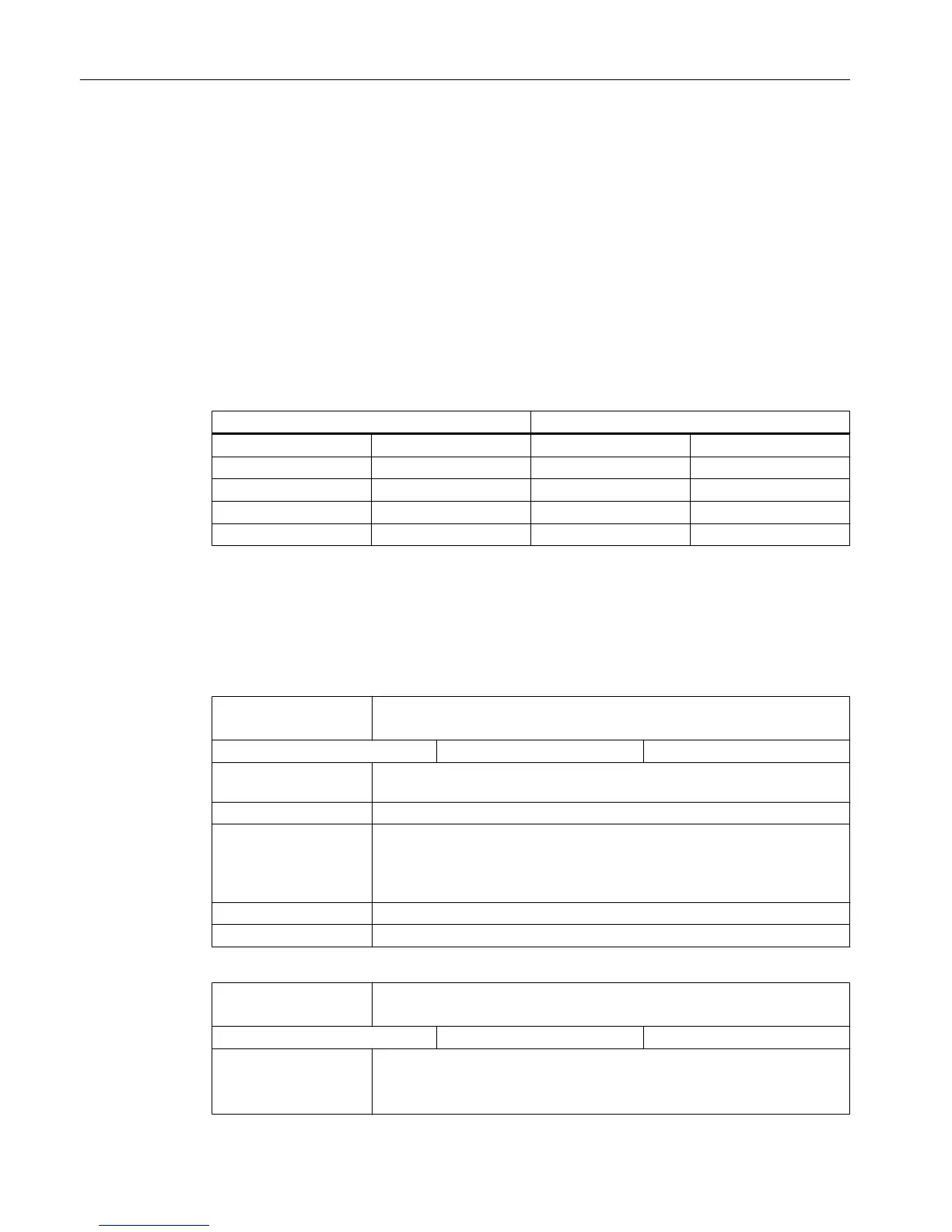
Notes on the PLC interface signal address representation
Currently, PLC interface signal addresses are represented by the V structure on the HMI while
the manual shows them by the DB structure.
See the following table for the relationship between the two representations.
V Structure DB Structure
Access Example Example Access
Bit V38000002.1 DB3800.DBX2.1 Bit
Byte VB38000002 DB3800.DBB2 Byte
Word VW38000002 DB3800.DBW2 Word
Double Word VD38000004 DB3800.DBD4 Double word
5.2 User alarm
Active alarm response
DB1600
DBX2000.0
NC start disable
Signal(s) from PLC → HMI
Edge evaluation: No Signal(s) updated: Cyclic
Signal state 1 The NC start disable prevents a part program from being started with the NC
start signal DB3200 DBX7.1 (NC start) == 1.
Signal state 0 The NC start disable is not active.
Special cases, errors, ... The start of a part program selected in the channel by part program command
START in another channel (program coordination) is not prevented by the
interface signal:
DB3200 DBX7.0 (NC start disable) == 1.
corresponding to ... IS "NC start"
Note for the reader
DB1600
DBX2000.1
Read-in disable
Signal(s) from PLC → HMI
Edge evaluation: No Signal(s) updated: Cyclic
Signal state 1 The main run reads in no more preprocessed part program blocks.
Note:
The signal is only active in the AUTOMATIC and MDI modes.
Detailed descriptions of interface signals
5.2 User alarm
Parameter Manual
376 List Manual, 01/2017

 Loading...


