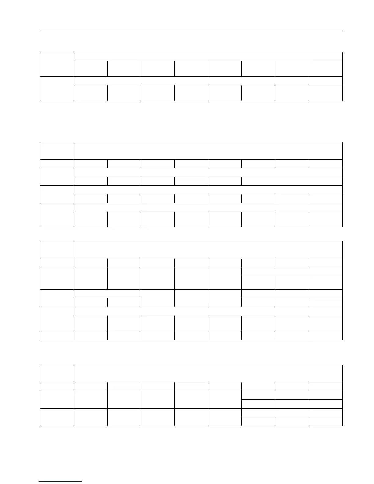
6 Value from PLC for digital NCK outputs
Output 8 Output 7 Output 6 Output 5 Output 4 Output 3 Output 2 Hardware
output
7 Setting mask for NCK outputs
Output 8 Output 7 Output 6 Output 5 Output 4 Output 3 Output 2 Hardware
output
6.9.4 Signals from fast inputs and outputs
DB2900 Signals from fast inputs and outputs [r]
NCK -> PLC interface
Byte Bit 7 Bit 6 Bit 5 Bit 4 Bit 3 Bit 2 Bit 1 Bit 0
0 Actual value for digital NCK inputs
Input 8 Input 7 Input 6 Input 5 Input 4 Hardware input
4 Setpoint for digital NCK outputs
Output 8 Output 7 Output 6 Output 5 Output 4 Output 3 Output 2 Hardware
output
DB3000 Mode signals to NCK [r/w]
PLC -> NCK interface
Byte Bit 7 Bit 6 Bit 5 Bit 4 Bit 3 Bit 2 Bit 1 Bit 0
0 Reset Mode
change
block
Mode
JOG MDI AUTO
1 Single block Machine function
Type A Type B REF
2 Machine function
1)
Continuous
traversing
Var. INC 10000 INC 1000 INC 100 INC 10 INC 1 INC
3
1)
To use the machine function signals in DB3000.DBB2, you must set the "INC inputs in the
operating-mode signal range active" signal (DB2600.DBX1.0) to "1".
DB3100 Mode signals from NCK [r]
NCK -> PLC interface
Byte Bit 7 Bit 6 Bit 5 Bit 4 Bit 3 Bit 2 Bit 1 Bit 0
0 Reset 808 READY Mode
JOG MDI AUTO
1 Active machine function
REF
PLC user interface
6.9 NCK signals
Parameter Manual
List Manual, 01/2017 489

 Loading...


