6.2 Signals from/to the MCP
Horizontal MCP with override switches
The
figure
below
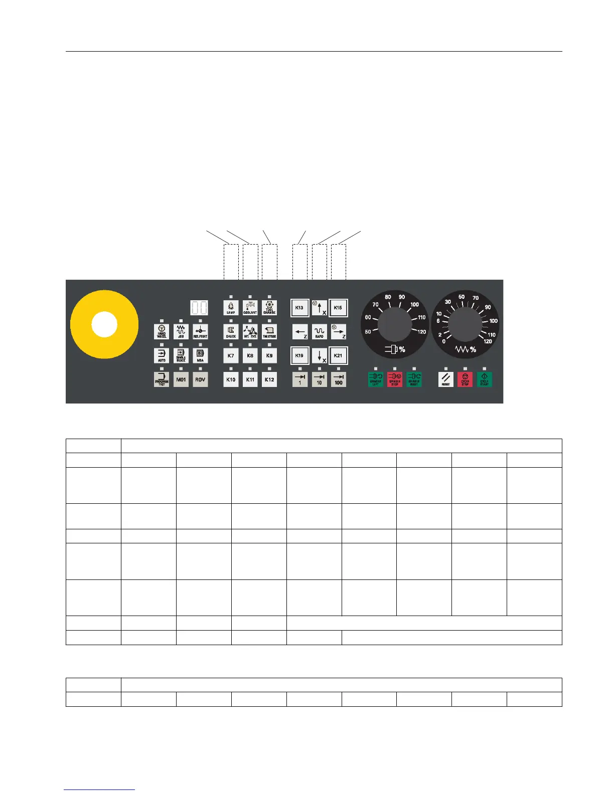
takes the horizontal MCP variant with override switches as an example. The
vertical MCP variants share the same PLC interface addresses for the corresponding keys.
Note that labels K13, K15, K19, and K21 are not included in the pre-inserted labeling strips for
keys of the MCP. The figure includes these labels so that when you read the information in
the following two tables, you know which keys on the MCP it refers to.
From the MCP
DB1000 From the MCP [r]
Byte Bit 7 Bit 6 Bit 5 Bit 4 Bit 3 Bit 2 Bit 1 Bit 0
0 M01 PRO‐
GRAM
TEST
MDA SINGLE
BLOCK
AUTO REF. POIN
T
JOG HAND
WHEEL
1 Key 7 TAIL
STOCK
INT. EXT. CHUCK TOOL
CHANGE
COOLANT LAMP ROV
2 100 (INC) 10 (INC) 1 (INC) Key 12 Key 11 Key 10 Key 9 Key 8
3 Axis tra‐
versing key
(↑x)
Key 13 CYCLE
START
CYCLE
STOP
RESET SPINDLE
RIGHT
SPINDLE
STOP
SPINDLE
LEFT
4 Key 21 Axis tra‐
versing key
(↓x)
Key 19 Axis tra‐
versing key
(→z)
RAPID Axis tra‐
versing key
(←z)
Key 15
8 Feed override value (in Gray code)
9 Spindle override value (in Gray code)
To the MCP
DB1100 To the MCP [r/w]
Byte Bit 7 Bit 6 Bit 5 Bit 4 Bit 3 Bit 2 Bit 1 Bit 0
PLC user interface
6.2 Signals from/to the MCP
Parameter Manual
List Manual, 01/2017 473

 Loading...


