•
Converts the measured current or voltage values into process values, for example, temperature, gas pres-
sure, etc.
•
Provides the recorded process variables for further processing by the fault recorder, the CFC, and in
GOOSE-applications for transmission via communication protocols, and for visualization
The fast measuring-transducer inputs are located on the IO212 module with 8 inputs (optionally current or
voltage inputs), and the IO210 module with 4 inputs (optionally current or voltage inputs).
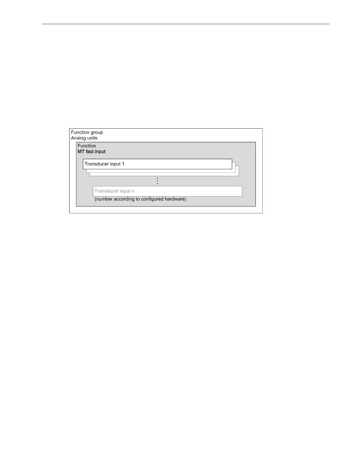
Structure of the Function
The function MT fast input works in the function group Analog units and contains the number of available
measuring-transducer inputs, depending on the hardware configuration. You can configure these channels
independently from one another either as current or voltage inputs.
[dw_mu-structure, 1, en_US]
Figure 6-51 Structure/Embedding of the Function
Function Description
Once you have instantiated the MT fast input function, it will be visible in the project tree in the function
group Analog units. You can find the function group Analog units in DIGSI in the Settings folder.
If you open the subdirectory MT fast input, you reach the setting sheet for the respective input (for more
details, see Application and Setting Notes).
The hardware is designed in such a way that either a current or a voltage can be processed at each input. Use
the corresponding terminals (see Hardware manual). Configure the input in accordance with the selected
connection (Parameter TD input-signal type). With the parameter Measuring window, you set the
measuring range with which the arithmetic mean value is determined. With the parameter Measuring
window, you also determine measurement speed for the input. For example, a setting of 100 ms means that
the measured value is updated every 100 ms.
6.5.6.2
6.5.6.3
Function-Group Types
6.5 Function-Group Type Analog Units
SIPROTEC 5, Fault Recorder, Manual 189
C53000-G5040-C018-5, Edition 11.2017

 Loading...


