Structure of the Function
Depending on the interconnection of the function groups, these can contain different measured-value groups.
A typical function group is displayed below.
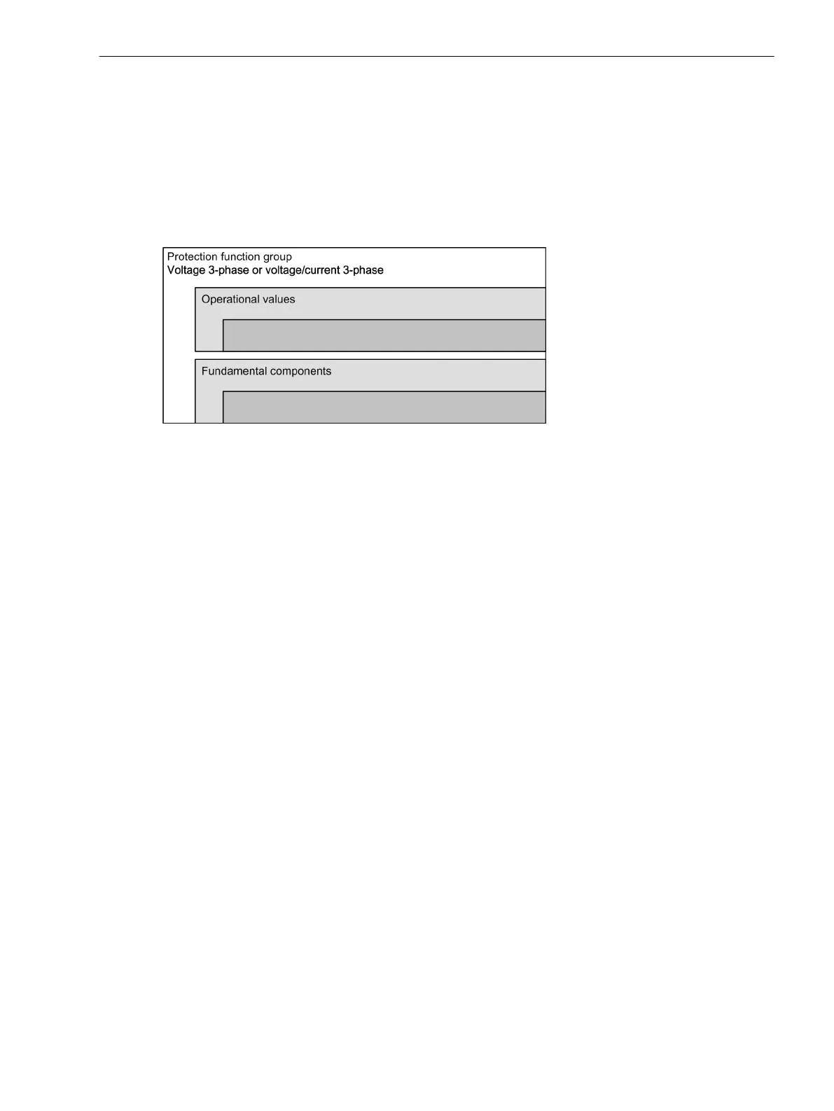
3-Phase Voltage and Voltage/Current 3-Phase Function Groups
In the simplest version, the 3-phase voltage and Voltage/current 3-phase function groups obtain the meas-
ured values of the 3-phase voltage and current system and contain the following measured-value groups:
[dwomvstr-110912-01.tif, 1, en_US]
Figure 9-2 Structure of Measured Values in Function Groups
The Operational measured values and Fundamental components measured value groups can be inserted
from the DIGSI 5 library into the 3-phase voltage and Voltage/current 3-phase function groups.
Details regarding the individual measured value groups can be found in the tables in the following chapters.
Inversion of Power-Related Measured Values
The calculated, directional values in the operational measured values (power, power factor, energy and
minimum, maximum, and average values based on these) are normally defined as positive in the direction of
the protected object. This requires that the connection polarity for the measuring points used be correctly set
(also compare Neutr.point in dir.of ref.obj parameter of the measuring point current, 3-phase). It
is, however, possible, to set the "forward" direction for the protection functions and the positive direction for
the powers, etc., differently, for example, such that the active power import (from the line to the busbar) is
displayed positively. Then set the option P, Q sign in the affected function groups on the reversed
parameter. With the parameter not reversed (default setting), the positive direction for power, etc., corre-
sponds to the "forward" direction for the protection functions.
The affected values are given in detail in Chapter 9.3 Operational Measured Values.
9.2
Measured and Energy Values
9.2 Structure of the Function
SIPROTEC 5, Fault Recorder, Manual 413
C53000-G5040-C018-5, Edition 11.2017

 Loading...


