CFC
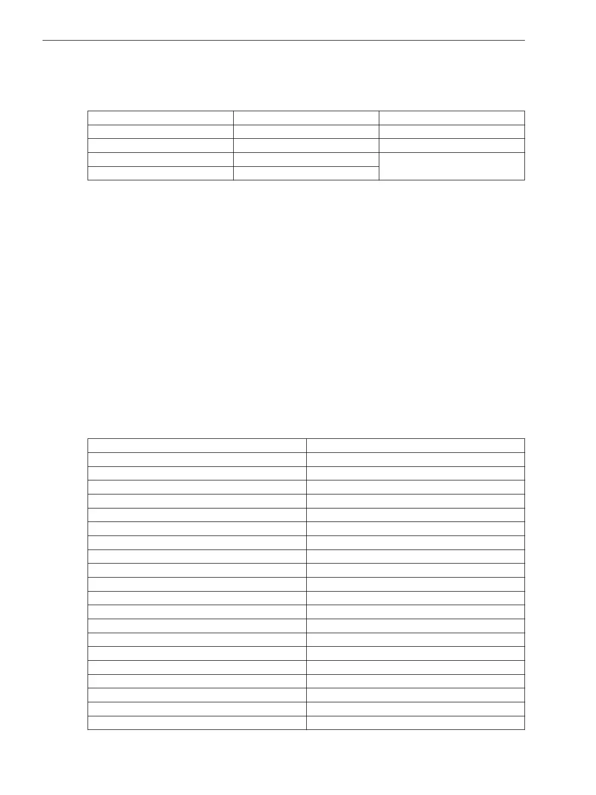
Typical response times and maximum number of ticks of the CFC task levels:
Task Level Time (in ms) Max. Number of Ticks CP300
Fast Event-Triggered
< 1 1500
Event-Triggered
<5 (<10 ms) 12 397
Interlocking
<5 (<10 ms) 28 656 in total
Measurement
250
The times describe the response time of a typical CFC chart at the respective task level. The maximum number
of ticks applies to a typical load for the device based on the application template Fault recorder N6: 1/1, 43
BI, 33 BO, 20I, 20V
The task level Measurement runs in cycles every 500 ms. All other task levels are event-triggered.
In order to estimate the tick consumption of a CFC chart, you can use the following formula:
T
chart
= 5 ∙ n
Inp
+ 5 ∙ n
Outp
+ T
TLev
+ ∑
i
T
int
+ ∑
j
T
Block
where:
n
Inp
Number of indications routed as input in the CFC chart
n
Outp
Number of indications routed as output in the CFC chart
T
TLev
101 Ticks in Fast Event-Triggered Level
104 Ticks in Event-Triggered Level
54 Ticks in Measurement Level
74 Ticks in Interlocking Level
T
int
Number of internal connections between 2 CFC blocks in one chart
T
Block
Used ticks per CFC block (see Technical Data)
Table 11-1 Ticks of the Individual CFC Blocks
Element Ticks
ABS_D 2.3
ABS_R 1.5
ACOS_R 6.9
ADD_D4 3.4
ADD_R4 3.3
ADD_XMV 6.4
ALARM 1.8
AND_SPS 1.1
AND10 2.9
APC_DEF 1.2
APC_EXE 1.0
APC_INFO 3.9
ASIN_R 1.3
ATAN_R 1.2
BLINK 1.3
BOOL_CNT 2.0
BOOL_INT 1.5
BSC_DEF 1.3
BSC_EXE 1.1
BSC_INFO 2.7
11.7
Technical Data
11.7 CFC
448 SIPROTEC 5, Fault Recorder, Manual
C53000-G5040-C018-5, Edition 11.2017

 Loading...


