Trigger Functions 3-Phase
Voltage Trigger
Overview of Functions
Voltage triggers start with exceeding or dropping below the set limiting values (level and gradient trigger) in
the fast-scan and slow-scan recorders. It is triggered by fundamental values, RMS values, or on symmetrical
components.
Structure of the Function
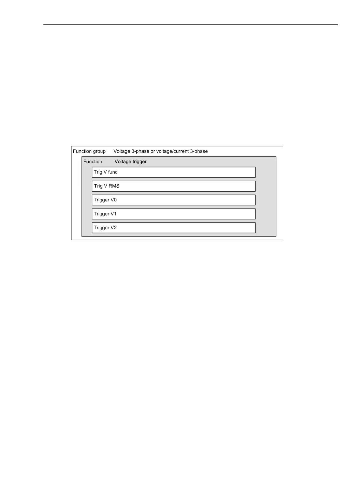
The function Voltage trigger is configurable in the 3-phase voltage and 3-phase voltage/current function
groups. The structure of the function Voltage trigger is shown in the following figure:
[dwfnvolt-161012-01.tif, 1, en_US]
Figure 7-61 Structure/Embedding of the 3-Phase Voltage or 3-Phase Voltage-Current Function
A maximum of 3 function blocks of the same type can be entered or removed within the function. In order to
distinguish the function blocks, they automatically receive a sequential number in the name of the function
block, e.g.,. V Fund. Trig 1, V Fund. Trig 2 and V Fund. Trig 3.
Each function block contains the level trigger Max. trigger and Min. trigger, as well as the gradient
trigger dM/dt rise (/Filter time) and dM/dt drop active of the corresponding measurand.
Function Description
Logic
The following logic diagram shows the operating state of a voltage trigger.
7.5
7.5.1
7.5.1.1
7.5.1.2
7.5.1.3
Fault Recorder
7.5 Trigger Functions 3-Phase
SIPROTEC 5, Fault Recorder, Manual 297
C53000-G5040-C018-5, Edition 11.2017

 Loading...


