GOOSE data type in a CFC chart to one trigger source. You can select the indications and their trigger condi-
tions on the basis of the imported SCD file (see IEC61850 Communication Protocol Manual).
For the GOOSE trigger, you preferably use the Boolean data type.
So that the indication can, for example, be routed to >External start, the GOOSE input must be routed via a
logic block chart (refer to the DIGSI 5 manual and following chapter).
Trigger Start Using Logic Block Chart
This function enables a modular, flexible combination of the trigger criteria. The following inputs and outputs
are supported:
•
Single-point and double-point indications
•
Analog values (absolute values or phases)
•
Boolean signals
•
GOOSE messages
The creation of CFC charts is described in detail in the DIGSI 5 manual. The CFC chart can be created in the
project tree under Plans.
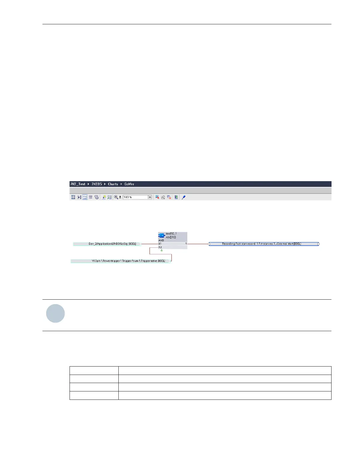
The trigger, that you select, for example, for the external or manual start of the fault record in the logic block
chart must in all cases be an AND operation.
[sccfctri-161012-01.tif, 1, en_US]
Figure 7-51 Example of a Logic Block Chart with AND Operation Trigger for External Start of the Fault
Record.
NOTE
If you have AND operation signals in the logic block chart, then avoid a single interconnection of these
signals in the Trigger routing, because this will remove this AND-operation.
Triggers on Indications
In the fast-scan and slow-scan recorders, it is possible to trigger on SPS indications and to record them.
The following routing options are available in the information routing:
Routing Symbol
Description
X The SPS indication is only routed.
T Triggering is done on the SPS indication.
XT Triggering is done on the SPS indication. The SPS indication is also recorded.
For triggering on binary inputs, the following procedure is recommended:
•
Open the DIGSI library.
•
Instantiate a user-defined function group.
•
Then add a user-defined function block to the user-defined function group.
7.3.3.4
7.3.3.5
Fault Recorder
7.3 Function Description Analog and Binary Triggers
SIPROTEC 5, Fault Recorder, Manual 269
C53000-G5040-C018-5, Edition 11.2017

 Loading...


