NOTE
For current-sum supervision, the ground current of the line to be protected must be connected to the 4th
current measurement input (I
N
).
Structure of the Function
The Current-sum supervision function is located in the Power-system data of each 3-phase current meas-
urement point.
[dwstrcss-300913, 2, en_US]
Figure 8-18 Structure/Embedding of the Function
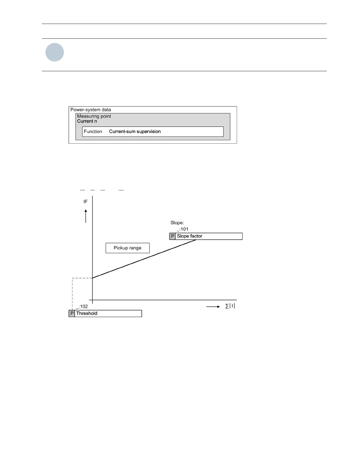
Function Description
The current sum is generated by addition of the current phasors. Errors in the current circuits are detected if
IF = |IA + IB + IC + kl• IN| > Threshold + Slope factor •Σ | I |.
[lokensum-300311-01.tif, 1, en_US]
Figure 8-19 Characteristic of the Current-Sum Supervision
8.3.7.2
8.3.7.3
Supervision Functions
8.3 Supervision of the Secondary System
SIPROTEC 5, Fault Recorder, Manual 387
C53000-G5040-C018-5, Edition 11.2017

 Loading...


