No. Information Data Class
(Type)
Type
Trig. I fund 1
_:9751:54 Trig. I fund 1:Inactive SPS O
_:9751:52 Trig. I fund 1:Behavior ENS O
_:9751:53 Trig. I fund 1:Health ENS O
_:9751:301 Trig. I fund 1:Trigger active SPS O
Frequency Trigger
Overview of Functions
Frequency triggers start with exceeding or dropping below the set limiting values (level and gradient trigger)
in the fast-scan and slow-scan recorders. It is triggered on the power frequency.
Structure of the Function
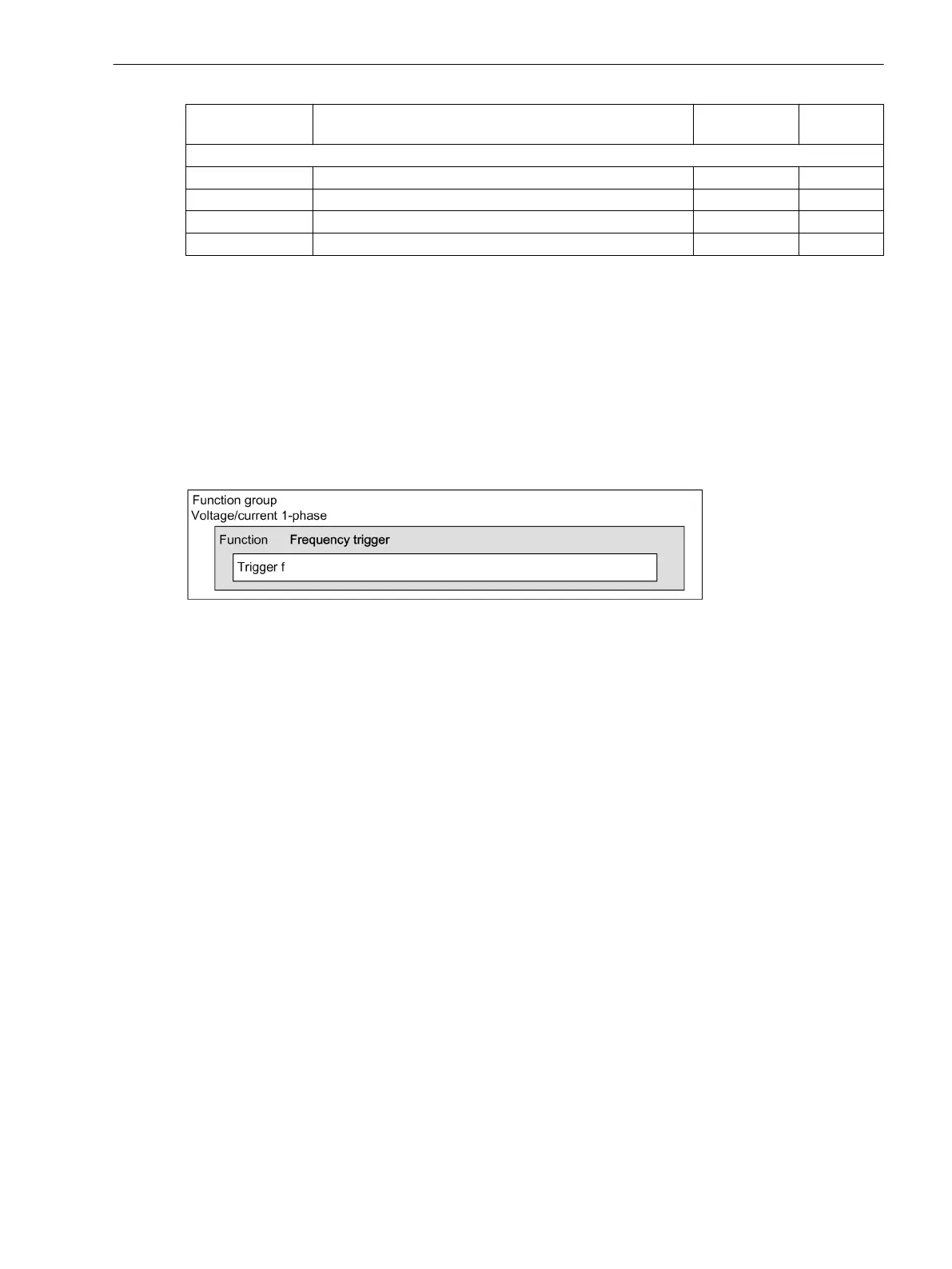
The Frequency trigger function can be configured in the Voltage/current 1-phase function group.
The structure of the function Frequency trigger is shown in the following figure:
[dw_frequency trigger 1-phase, 1, en_US]
Figure 7-57 Structure/Embedding of the Function
A maximum of 3 function blocks of the same type can be entered or removed within the function. For unam-
biguous differentiation, the function blocks automatically receive a sequential number in the name of the
function block, for example, Frq. Trigger 1, Frq. Trigger 2, Frq. Trigger 3.
Each function block contains the level triggers Max. trigger and Min. trigger, as well as the gradient
triggers dM/dt rise (/Filter time) and dM/dt drop active of the corresponding measurand.
Function Description
Logic
The following logic diagram shows the operating state of the frequency trigger.
7.4.3
7.4.3.1
7.4.3.2
7.4.3.3
Fault Recorder
7.4 Trigger Functions 1-Phase
SIPROTEC 5, Fault Recorder, Manual 285
C53000-G5040-C018-5, Edition 11.2017

 Loading...


