[dw_current trigger 1-phase, 1, en_US]
Figure 7-55 Structure/Embedding of the Voltage/Current 1-Phase Function
A maximum of 3 function blocks of the same type can be entered or removed within the function. For unam-
biguous differentiation the function blocks automatically receive a sequential number in the name of the func-
tion block, for example, Trig I RMS 1, Trig I RMS 2, and Trig I RMS 3.
Each function block contains the level triggers Max. trigger and Min. trigger, as well as the gradient
triggers dM/dt rise (/Filter time) and dM/dt drop active of the corresponding measurand.
Function Description
Logic
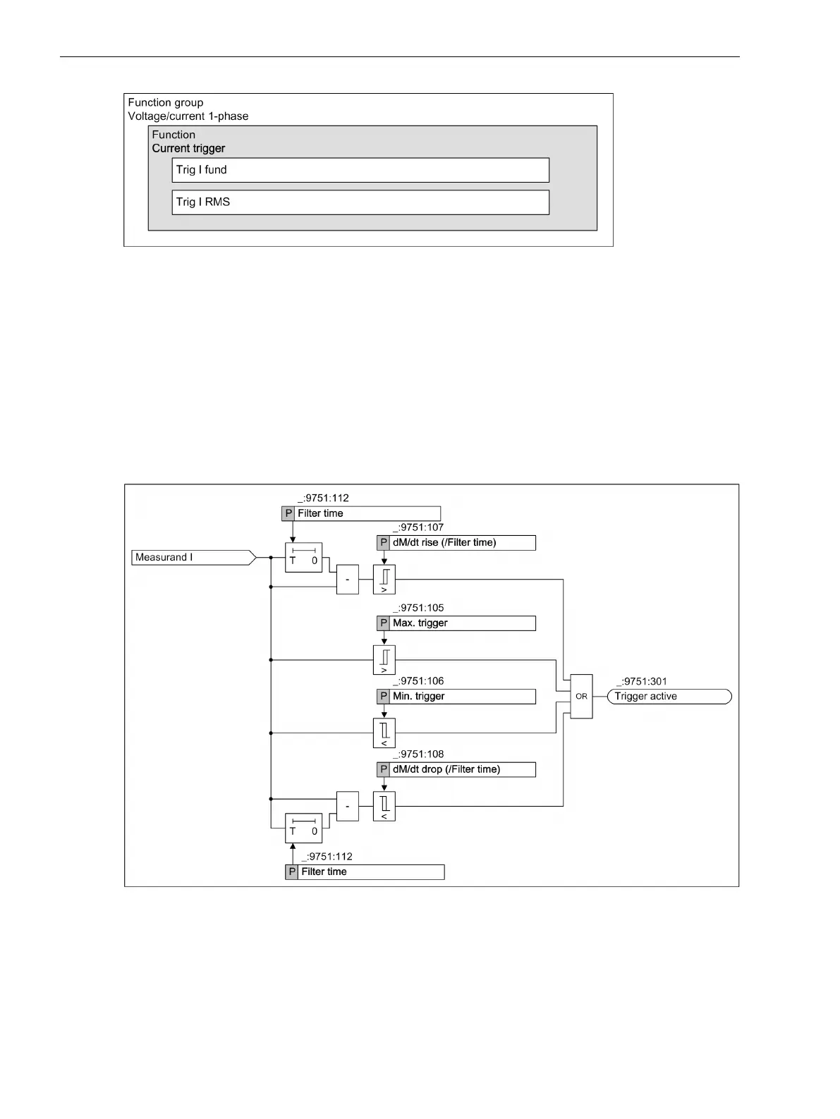
The following logic diagram shows the operating state of the current trigger.
[dwlotrii-161012-01.tif, 1, en_US]
Figure 7-56
Logic Diagrams of the Current Trigger
The function Current trigger is subdivided intoLevel and Gradient trigger.
The Level trigger monitors the measurand for minimum and maximum limit violations. The Gradient trigger
monitors the positive slope (increasing) and the negative slope (decreasing) of the measurand for a limit viola-
tion. The gradient is formed based on the set filtering time.
7.4.2.3
Fault Recorder
7.4 Trigger Functions 1-Phase
278 SIPROTEC 5, Fault Recorder, Manual
C53000-G5040-C018-5, Edition 11.2017

 Loading...


