Shielding Concept
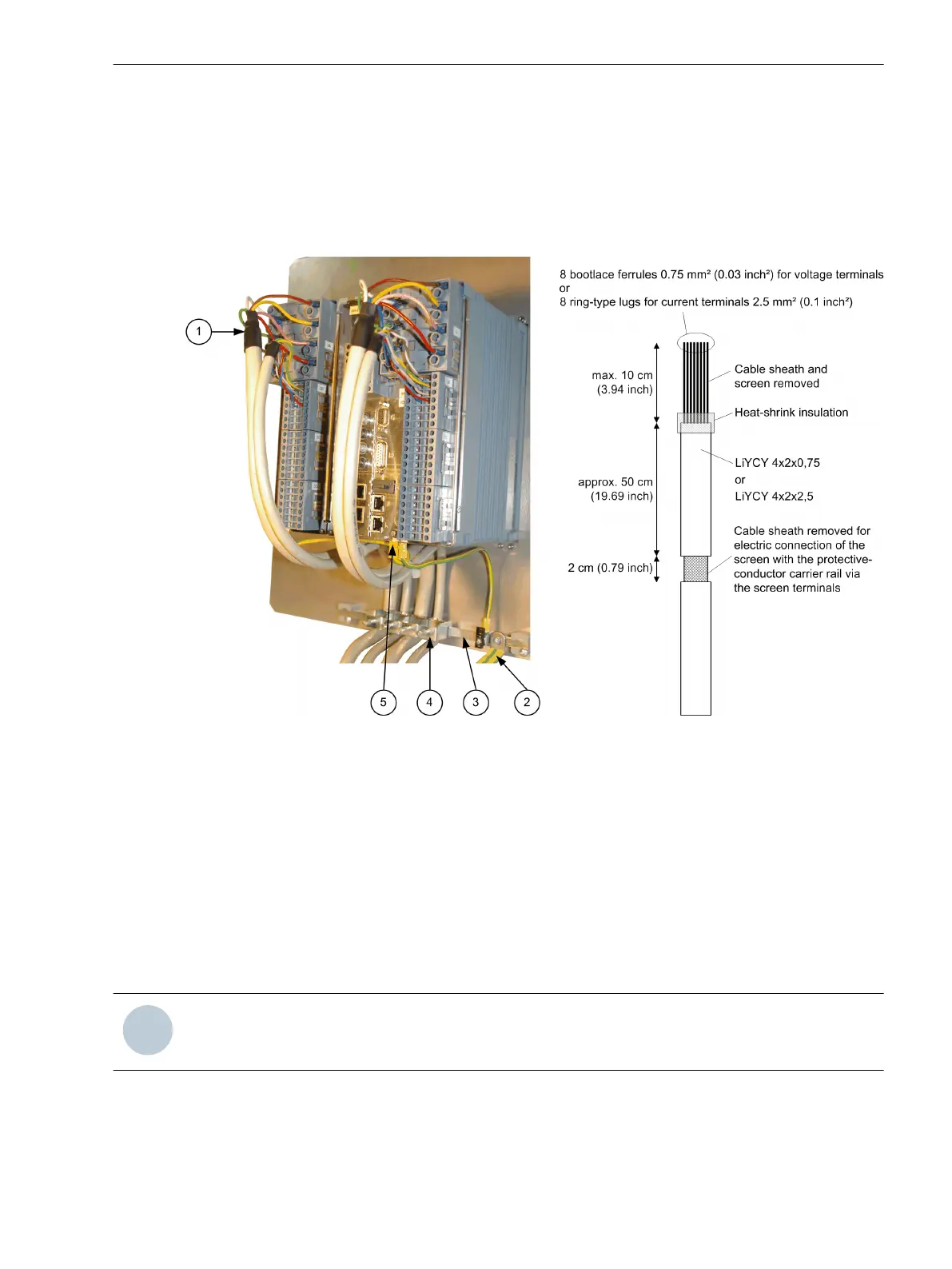
The measuring accuracy of the fault recorder can only be maintained if the voltage and current signals are
connected to the device using shielded lines (1).
Siemens recommends stopping the cable shield at a maximum of 10 cm before the device terminals (1) and
connecting the cable shields near the device with low impedance via the shield terminals (4) to ground poten-
tial (2).
[dwbackvi-130213-01.tif, 2, en_US]
Figure A-19
Shielding Concept
(1) Shielded lines
(2)
To the main grounding busbar, cross-section at least 16 mm
2
(3) Protective-conductor carrier rail
(4) Shield terminal
(5) Protective-conductor terminal of the device
•
Recommended control line for voltage signals: 4•2•0.75 mm
2
stranded shielded pair, for example,
LiYCY 4x2x0.75
•
Recommended control line for current signals: 4•2•2.5 mm
2
stranded shielded pair, for example,
LiYCY 4x2x2.5
NOTE
Make sure not to damage the cable shield!
A.7
Appendix
A.7 Shielding Concept
SIPROTEC 5, Fault Recorder, Manual 471
C53000-G5040-C018-5, Edition 11.2017

 Loading...


